Hubbell Load:Logic Installation Instructions Manual Download Page 10


PD2794                                 02/2017 

                                                                                                                     Page 5 

How to Enter Manual Configuration Mode from the Room Controller 

 
To enter manual configuration mode, follow these steps: 
 

1.  Simultaneously press and hold the A and B pushbuttons on the room controller until the A and B LED

’s start to blink 

alternately. 

2.  Release the A and B pushbuttons.  The room controller is now in manual configuration mode.  The light fixtures on the 

circuit connected to Load A will be ON and all other loads will be OFF. 


Note:

 While in configuration mode no more than one load will ever be ON and the A and B buttons on the room controller will 

NOT be able to control the loads.  

 
Hint: If both loads (A and B) are ON or pressing the A or B button switches a load, the room controller is NOT in 
configuration mode.  Repeat the previous steps to enter manual configuration mode.


Exit Manual Configuration Mode from the Room Controller


To exit manual configuration mode, simultaneously press and immediately release buttons A and B.  The room controller will 
resume normal operation. 
 

Enter Manual Configuration Mode from a Switch


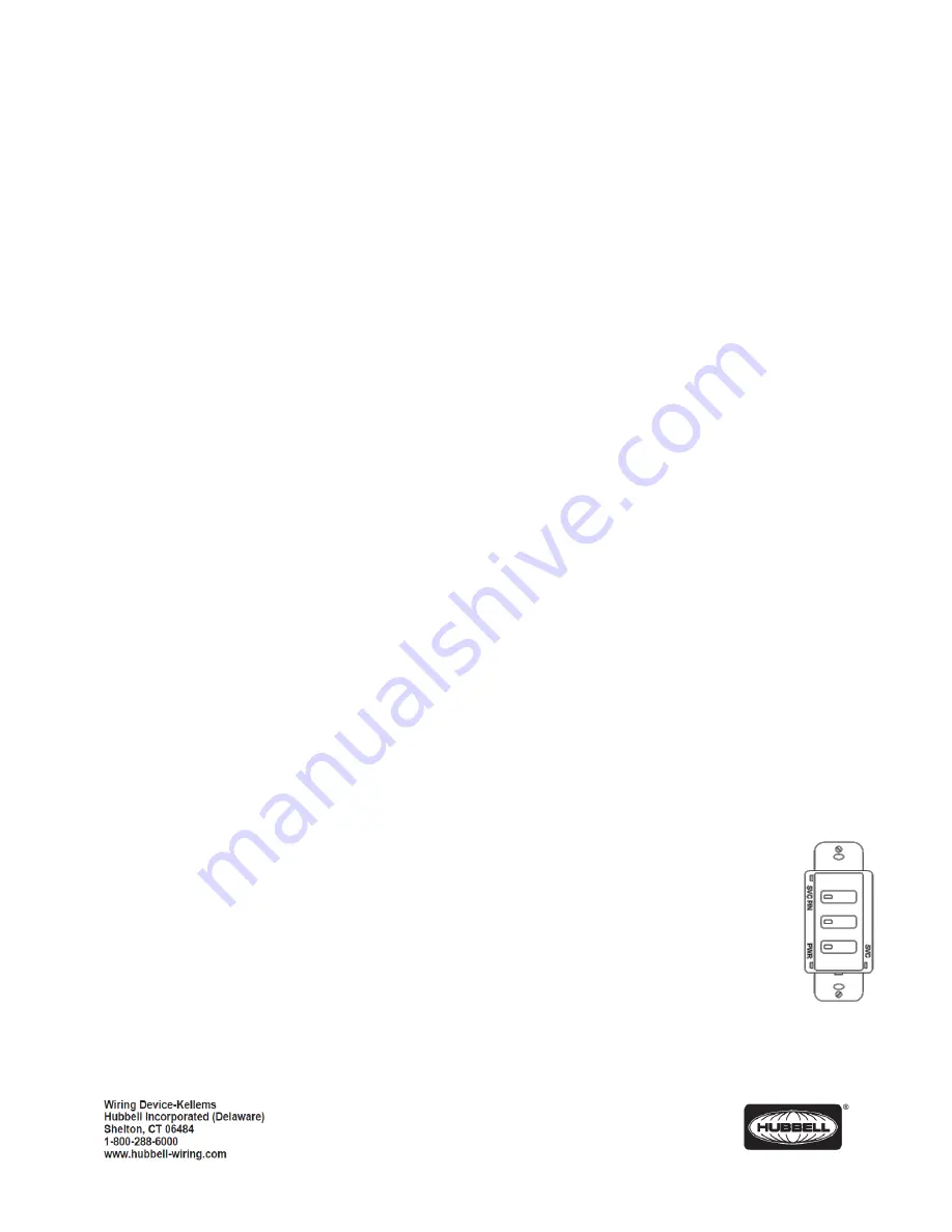
1.  Remove the faceplate from any of the switches in the room and locate the rectangular opening in the plastic bezel 

marked “SVC PIN”.  Use a small round object such as a straightened paper clip to press the recessed configuration 
button for 5 seconds. 

2.  Observe that the button is located slightly offset from the bezel opening.  The L

ED marked “SVC” will blink while the 

configuration button is being pressed. 

3.  Release the configuration button and note that one load turns ON and all other loads turn OFF indicating that the room 

is in manual configuration mode. 

 
Exit Manual Configuration Mode from a Switch


1.  Press the configuration button for five seconds.  T

he LED marked “SVC” will blink while the configuration button is 

being pressed. 

2.  Release the configuration button. The loads in the room will restore to the levels they were prior to entering manual 

configuration mode. 


Assigning a Lighting Load to Buttons in a Switch 

 
As described in the 

Smart Switches 

section, all switches assume a default operation of the loads when they are connected to 

the room controller

’s RJ45 port.  The assignment of the loads to the buttons can easily be changed as follows: 

 
Switches with LED indicators: 
 

1.  Enter in 

Manual Configuration Mode from the Switch

 described above.  Load A will be ON.  While 

load A is ON, each button that controls that load will have a lighted LED.


2.  To deny the control function of the load from the button, press the switch button to turn OFF the 

button’s LED. 

3.  To assign control of the load to another b

utton, press the switch’s button to light ON the LED the 

button to be paired. 

4.  Repeat this process for all buttons. 
5.  To advance to the next load, press and release button A on the room controller.  Load A will turn OFF and the next 

load will turn ON. 

Summary of Contents for Load:Logic

Page 1: ...unit For Indoor use only Do not use outdoors Disconnect switch or a circuit breaker must be provided and marked as the disconnecting device The use of accessory equipment not recommended by the manuf...

Page 2: ...splayed These will include 1 Room Controllers Touch to display a list of room controllers found in the room Touch one of the room controllers to see a display showing controls for the relay s and dimm...

Page 3: ...ion after an outage Last State is the default setting Touch Set Level to enter a specific dim level for power up Use the Level slider to set the desired level or touch the box to use the keyboard to e...

Page 4: ...Groups A blue background fill in one of the 16 available groups indicates that this switch is selected to be a member of this group number A gray background fill indicates that the switch is NOT a me...

Page 5: ...ne of the 16 available groups indicates that this sensor is selected to be a member of this group number A gray background fill indicates that the sensor is NOT a member of the group By default the oc...

Page 6: ...urned OFF NOTE Make adjustments to the Design Level until the desired foot candle reading is achieved on the light meter at the task surface E Test Mode This is the factory default setting for Zone 1...

Page 7: ...rcuit s it controls The MAC address will be needed later during the system setup process 3 Turn power OFF at the service panel 4 Mount the room controller s enclosure to a knockout opening of an elect...

Page 8: ...Occupancy sensor with RP option 4 Loads NOTE Only one daylight sensor can be connected in each room zone Self Configuration The room controller s sequence of operation will automatically reconfigure...

Page 9: ...s RCSNFx and RCSTOx RCSRLx RCSSCx RCSNRLFx will self configure by default to their respective descriptions For example RCSRLx is a Raise Lower dimmer Its default operation will be to change ALL the li...

Page 10: ...2 Observe that the button is located slightly offset from the bezel opening The LED marked SVC will blink while the configuration button is being pressed 3 Release the configuration button and note t...

Page 11: ...Simultaneously press and hold buttons A and B for three seconds until LED A begins to blink rapidly This indicates the room controller has transitioned from load configuration mode into photocell con...

Page 12: ...n is complete the room controller will automatically exit configuration mode and return to normal operation Daylight harvesting will now be active based on the settings made during configuration Reset...

Reviews: