background image

UPS5000-E-(40 kVA-320 kVA) 
User Manual 

5 Operations 


Issue 10 (2015-09-15) 

Huawei Proprietary and Confidential                                     

Copyright © Huawei Technologies Co., Ltd. 

167 


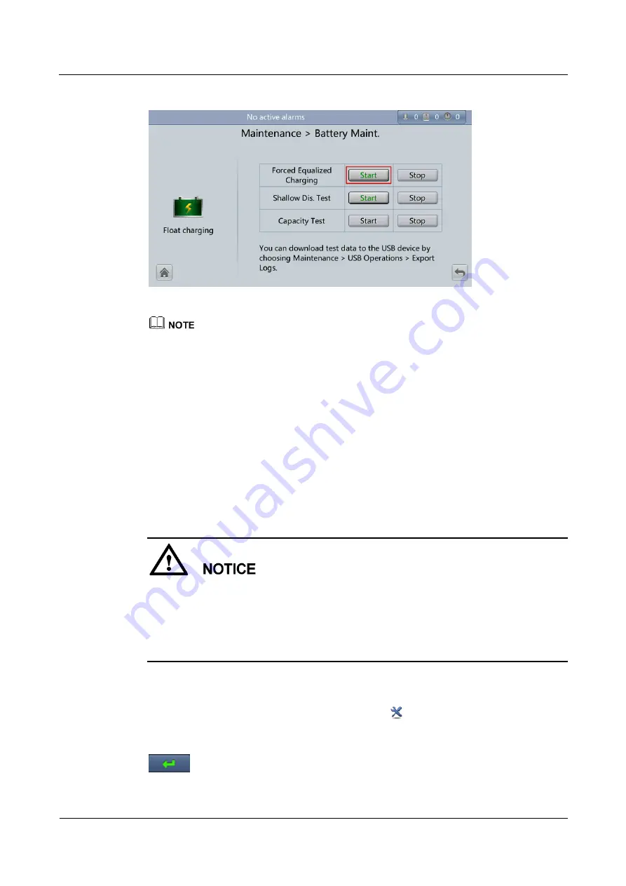
Figure 5-23


Starting a forced equalized charge test 


The forced equalized charge test stops in any of the following cases: 


The forced equalized charge test duration reaches the forced equalized charge protection time 
(12–24 h, 18 h by default). 


The UPS generates a battery overtemperature, overvoltage, or overcurrent alarm. 


The UPS generates an alarm. 

You tap 

Stop

 on the right of 

Forced Equalized Charging

----End 

5.6.2 Shallow Discharge Test 

Context 


Before a shallow discharge test, ensure that: 


The UPS works in normal mode at a stable load rate with a change rate less than 10%. 


The UPS has generated no battery overtemperature, overvoltage, or overcurrent alarm. No 
generator is connected to the UPS. 


The mains, batteries, charger, and discharger are normal. No overload alarm is generated. 

Procedure 

Step 1


On the main screen of the LCD, tap 

System Info

. Tap

. The 

Maintenance

 screen is 

displayed. 

Step 2


(Optional) If you have not logged in, enter a user name and a password, and then tap 

Summary of Contents for 0K-F120

Page 1: ...Part number 31010LMQ UPS5000 E 40 kVA 320 kVA User Manual Issue 10 Date 2015 09 15 HUAWEI TECHNOLOGIES CO LTD ...

Page 2: ... Huawei and the customer All or part of the products services and features described in this document may not be within the purchase scope or the usage scope Unless otherwise specified in the contract all statements information and recommendations in this document are provided AS IS without warranties guarantees or representations of any kind either express or implied The information in this docum...

Page 3: ...Hardware installation engineers Commissioning engineers Data configuration engineers Maintenance engineers Symbol Conventions The symbols that may be found in this document are defined as follows Symbol Description Indicates an imminently hazardous situation which if not avoided will result in death or serious injury Indicates a potentially hazardous situation which if not avoided could result in ...

Page 4: ...document issue contains all the changes made in earlier issues Issue 10 2015 09 15 Upgraded the software version and added the description of the UPS5000 E 320K F320T Issue 09 2015 08 20 Deleted V100R001 from the version information Issue 08 2015 04 02 Updated the Monitoring screen image Issue 07 2014 10 31 Modified some pictures based on Issue 06 Issue 06 2014 09 02 Optimized the document archite...

Page 5: ...UPS5000 E 40 kVA 320 kVA User Manual About This Document Issue 10 2015 09 15 Huawei Proprietary and Confidential Copyright Huawei Technologies Co Ltd iv Issue 01 2013 06 15 This is the first release ...

Page 6: ...ion 11 2 2 Benefits 12 2 3 Working Principle 13 2 3 1 Conceptual Diagram 13 2 3 2 Working Modes 14 2 3 2 1 Normal Mode 14 2 3 2 2 Bypass Mode 15 2 3 2 3 Battery Mode 16 2 3 2 4 Maintenance Bypass Mode 17 2 3 2 5 ECO Mode 18 2 4 Overview 19 2 4 1 Structure 19 2 4 2 Control Module 21 2 4 2 1 Overview 21 2 4 2 2 ECM 22 2 4 2 3 Dry contact card 23 2 4 2 4 Optional Backfeed Protection Card 25 2 4 2 5 O...

Page 7: ...3 2 7 Installing Batteries 54 3 2 8 Routing Cables 57 3 2 8 1 Top Cable Routing 57 3 2 8 2 Bottom Cable Routing 68 3 2 9 Connecting Ground Cables 71 3 2 10 Connecting AC Input Power Cables 73 3 2 10 1 Single Mains 73 3 2 10 2 Dual Mains 75 3 2 11 Connecting AC Output Power Cables 79 3 2 12 Connecting Battery Cables 81 3 2 13 Connecting Signal Cables 84 3 2 13 1 Optional Connecting a Battery Ground...

Page 8: ... 138 4 2 1 Login 138 4 2 2 Monitoring Page 140 4 2 2 1 Active Alarms Page 141 4 2 2 2 Real time Data Page 142 4 2 2 3 Param Settings Page 142 4 2 2 4 Comm Config Page 143 4 2 2 5 Control Page 143 4 2 3 Query Page 144 4 2 3 1 Historical Alarms Page 144 4 2 3 2 Logs Page 145 4 2 4 Config Page 145 4 2 5 Maint Page 146 5 Operations 149 5 1 Powering On and Starting the UPS 149 5 2 Shutting Down and Pow...

Page 9: ...intenance 196 6 1 1 Monthly Maintenance 196 6 1 2 Quarterly Maintenance 197 6 1 3 Yearly Maintenance 197 6 2 Battery Maintenance 199 6 2 1 Precautions 199 6 2 2 Monthly Maintenance 199 6 2 3 Quarterly Maintenance 200 6 2 4 Yearly Maintenance 201 7 Troubleshooting 203 8 Technical Specifications 205 8 1 Physical Specifications 205 8 2 Environmental Specifications 206 8 3 Safety Regulations and EMC 2...

Page 10: ...d they must understand basic safety precautions to avoid hazards To ensure safety of humans and the equipment pay attention to the safety symbols on the equipment and all the safety instructions in this document Huawei will not be liable for any consequence caused by the violation of the safety operation regulations and design production and usage standards Declaration Huawei does not take respons...

Page 11: ...qualified personnel are allowed to remove safety facilities and inspect the equipment Only personnel certified or authorized by Huawei are allowed to replace or change the devices or components including software Installation personnel must report faults or errors that might cause serious safety issues to related owners This product should be installed and used by following the specification requi...

Page 12: ...interferences If you use the UPS for life supporting medical apparatus and facilities such as lifts where adequate care has to be taken to ensure personal security discuss with the manufacturer in advance about the applicability settings management and maintenance of the UPS which require special considerations during design Device Security Before operation ensure that the device is firmly anchore...

Page 13: ...ns Avoid using ordinary tools When the operation is performed in a damp environment ensure that the device is dry When water is found in the rack or the rack is damp switch off the power supply immediately High Electrical Leakage Ground the device before powering it on Otherwise personal injury or device damage may be caused by high leakage current If a high electrical leakage tag is attached to t...

Page 14: ... labels on the mains and bypass input circuit breakers informing that the UPS is connected to backfeed protection circuits Disconnect the backfeed protection card from the UPS before performing operations on the UPS Electrostatic Discharge The static electricity generated by human bodies may damage the electrostatic sensitive components on boards for example the large scale integrated LSI circuits...

Page 15: ...he following environments Places where the temperature and humidity are beyond the range of 0 40 C and 0 95 RH respectively Places in direct sunlight or near heat sources Places subject to vibrations or shocks Dusty places or places exposed to corrosive substances salts or flammable gases Sea environments or outdoor land environments with simple shielding measures near pollution sources If a site ...

Page 16: ...and circuit boards and ultimately damage the device and cause short circuits of circuit boards Short circuits caused by incorrect operations may cause serious injuries due to high power of batteries Do not reversely connect positive and negative battery terminals Use batteries of the specified type Otherwise the batteries may be damaged Check battery connections periodically to ensure that all scr...

Page 17: ... and maintenance Short Circuit Battery short circuits may cause human injuries Although the voltage of ordinary batteries is low the instantaneous high current caused by the short circuit releases a great deal of energy To avoid battery short circuits do not maintain batteries in use Harmful Gas Do not use unsealed lead acid batteries Place and secure lead acid batteries horizontally to avoid infl...

Page 18: ... and absorb the leaking electrolyte Sodium bicarbonate baking soda NaHCO3 Sodium carbonate soda Na2CO3 When using substances to counteract and absorb electrolytes strictly follow the guidelines provided by the battery supplier If your body meets the acid wash the part that has met the acid with clean water immediately or immediately call a doctor if the situation is serious 1 5 Mechanical Safety M...

Page 19: ... have been stored in a temperature lower than 0 C 32 F move the cables to an environment of the ambient temperature and store them at the ambient temperature for at least 24 hours Handle cables with caution especially at a low temperature Do not drop the cables directly from the vehicle As the insulation layer of a cable may age or be damaged at high temperatures ensure a sufficient distance betwe...

Page 20: ...Figure 2 1 UPS model number Table 2 1 Model number details No Item Description 1 Product category UPS 2 UPS family 5000 3 UPS subcategory E 4 Output capacity 120K 120 kVA 200K 200 kVA 320K 320 kVA 5 Rack type F120 120 kVA rack F200 200 kVA rack F320 320 kVA rack 6 Cable routing Routed from the top only the UPS5000 E 320K F320T model contains T This document describes the following UPS models UPS50...

Page 21: ... to a maximum of 320 kVA and is at least 40 kVA When mentioning the UPS5000 E 320K F320 this document emphasizes its output capacity of 240 kVA 280 kVA or 320 kVA Cables are routed from the top 2 2 Benefits High Stability and Reliability The UPS is suitable for poor power grids because it supports a wide range of input frequencies which is 40 70 Hz The UPS works at full load when the line voltage ...

Page 22: ... space UPS5000 E 120K F120 and UPS5000 E 200K F200 allows you to route cables from the top and bottom The UPS5000 E 320K F320 allows you to route cables from the bottom if you install a top entry cabinet you can also route cables from the top The UPS5000 E 320K F320T supports cable routing from the top A user friendly 7 inch liquid crystal display LCD provides the UPS5000 E status and operating da...

Page 23: ...nceptual diagram 2 3 2 Working Modes 2 3 2 1 Normal Mode In normal mode the rectifier converts AC power into DC power Then the inverter converts DC power into high precision AC outputs The conversions protect loads from interference such as input harmonics glitches and voltage transients Figure 2 3 shows the conceptual diagram of the UPS working in normal mode ...

Page 24: ... 2 3 2 2 Bypass Mode The UPS automatically transfers to bypass mode upon detecting power module overtemperature overload or other faults that may cause the inverter to shut down The bypass power supply is not protected by the UPS and therefore tends to be affected by mains outages and abnormal AC voltage and frequency Figure 2 4 shows the conceptual diagram of the UPS working in bypass mode ...

Page 25: ...s Co Ltd 16 Figure 2 4 UPS conceptual diagram in bypass mode 2 3 2 3 Battery Mode If the rectifier input voltage is abnormal the UPS transfers to battery mode The power module obtains DC power from batteries which is converted into AC outputs by the inverter Figure 2 5 shows the conceptual diagram of the UPS working in battery mode ...

Page 26: ...Figure 2 5 UPS conceptual diagram in battery mode 2 3 2 4 Maintenance Bypass Mode In maintenance bypass mode the current flows through maintenance bypass circuits instead of the power module or bypass module You can perform maintenance on the UPS in this mode Figure 2 6 shows the conceptual diagram of the UPS working in maintenance bypass mode ...

Page 27: ...In ECO mode when the bypass input voltage is within the ECO voltage range the static bypass switch turns on and the bypass supplies power manual startup is required to ensure that the inverter is in standby state and the power flow has reached the inverter When the bypass input voltage is out of the ECO voltage range the UPS transfers from bypass mode to normal mode In bypass mode or normal mode t...

Page 28: ...prietary and Confidential Copyright Huawei Technologies Co Ltd 19 Figure 2 7 UPS conceptual diagram in ECO mode 2 4 Overview 2 4 1 Structure Figure 2 8 shows the front view of the UPS5000 E 200K F200 cabinet and Figure 2 9 shows the front view of the UPS5000 E 320K F320T cabinet ...

Page 29: ...Figure 2 8 UPS5000 E 200K F200 front view with the door open 1 Filler panels 2 Monitor display unit MDU 3 Maintenance bypass switch 4 Power distribution subrack cover 5 Control Module CM 6 Bypass module 7 Power modules The UPS5000 E 200K F200 is used as an example to introduce the UPS5000 E 120K F120 UPS5000 E 200K F200 and UPS5000 E 320K F320 ...

Page 30: ... Maintenance bypass switch 3 Filler panels 4 CM 5 Bypass module 6 Power modules 7 MDU 2 4 2 Control Module 2 4 2 1 Overview In a standard configuration the CM provides two ECMs one dry contact card and one monitoring interface card from left to right The cards are hot swappable One subrack is reserved above the dry contact card You can insert a backfeed protection card or dry contact extended card...

Page 31: ... port 18 Optional card subrack cover 2 4 2 2 ECM The CM provides two active standby energy control modules ECMs Each ECM provides one BSC port and one parallel port as shown in Figure 2 11 Figure 2 11 ECM To connect UPSs in parallel use a parallel cable to connect the parallel ports on the ECMs on the two UPSs A hot swappable BSC is used in a dual bus system to process the communication informatio...

Page 32: ...aker BCB box and implement remote emergency power off EPO The maximum voltage current is 12 V 200 mA or 5 V 100 mA Figure 2 12 shows the signal ports on the dry contact card Figure 2 12 Dry contact card Table 2 3 describes the ports on the dry contact card Table 2 3 Ports on the dry contact card Port Silk Screen Description Status BTG Detects battery ground failures Status Connected battery ground...

Page 33: ... port is disconnected from the EPO_12V port EPO is triggered 12 V 12 V SWIT CH STAT US OUT Monitors the UPS output circuit breaker on the output power distribution cabinet PDC Status Disconnected circuit breaker OFF Connected circuit breaker ON The initial status is Connected 0 V Secondary side ground MT Monitors the maintenance circuit breaker on the output PDC Status Disconnected circuit breaker...

Page 34: ...l as monitoring and control functions for the MDU The ports include the ambient temperature and humidity sensor port battery monitoring unit BMU port FE port battery temperature monitoring port and network management port Interworking with the monitoring interface card the MDU monitors the UPS configures parameters delivers commands reports information and displays the UPS key information and para...

Page 35: ...icates D G control which cannot be changed COM DB26 MDU Provides FE RS485 Inter Integrated Circuit I2C and control area network CAN signals Battery temperatur e sensor port B_TEMP Connects to an indoor battery temperature sensor This port can connect to a short distance battery temperature sensor Southboun d port 2 COM2 Connects to a southbound device such as a BMU Southboun d port 1 COM1 Connects...

Page 36: ...nt loads in large and medium sized equipment rooms and data centers The dual bus system is highly reliable but its configuration is complex A 1 1 parallel system is a typical configuration You can set the number of requisite UPSs and redundant ones on the LCD and WebUI 2 5 1 Single UPS The UPS5000 E has a modular structure Its power modules are connected in parallel to deliver a high loading capab...

Page 37: ... or more UPSs connected in parallel The dual bus system is highly reliable and is suitable for loads with multiple input terminals You can install a static transfer switch STS to start the bus synchronization controller BSC while the STS is optional and the BSC is a standard configuration Of the two UPS systems one is a master system and the other is a slave system The UPS systems work in normal m...

Page 38: ...des two 4 pole 400 A input MCCBs and one 3 pole 630 A maintenance bypass circuit breaker Measures and displays electrical parameters such as the three phase input voltage current and PF Provides signal ports to report the status of circuit breakers and provides three phase power indicators to display the power status BCB box PDC 0250DC0384BXA PDC 0400DC0384BXA PDC 0630DC0384BXA PDU8000 0125DCV8 B ...

Page 39: ...hat the cabinet meets the requirements of 9 degree seismic fortification intensity IP21 component N A Prevents water from dropping into the cabinet protecting the cabinet to IP21 Top outlet kit N A If you need to install the cabinet against a wall install a top outlet kit to meet heat dissipation requirements Top entry cabinet N A Install a top entry cabinet to route cables from the top of the UPS...

Page 40: ...60 m Transmits bus synchronization signals in a dual bus system The ECM extended subrack does not support onsite installation If you require this optional component inform Huawei when you purchase the UPS Huawei installs it before delivery The top entry cabinet applies only to the UPS5000 E 320K F320 The input PDC output PDC and top outlet kit component apply only to the UPS5000 E 120K F120 and UP...

Page 41: ...e UPS5000 E batteries and battery racks The weight of batteries and battery racks depends on the UPS configuration for the site Table 3 1 lists the UPS5000 E weight Table 3 1 UPS weight Model Capacity Weight UPS5000 E 120K F120 40 kVA 256 5 kg 80 kVA 289 0 kg 120 kVA 321 5 kg UPS5000 E 200K F200 160 kVA 354 0 kg 200 kVA 386 5 kg UPS5000 E 320K F320 UPS5 000 E 320K F320T 40 kVA 256 5 kg 80 kVA 289 ...

Page 42: ... 10 2015 09 15 Huawei Proprietary and Confidential Copyright Huawei Technologies Co Ltd 33 Figure 3 1 shows the installation dimensions Figure 3 1 Dimensions unit mm 1 Front door 2 Foot 3 Caster 4 Base 5 Rear panel 6 Base installation hole 7 Beam 8 Side post ...

Page 43: ... temperatures for valve regulated lead acid VRLA batteries are 20 30 C Operating temperatures higher than 30 C shorten the battery lifespan and operating temperatures lower than 20 C reduce the battery backup time 3 1 1 3 Installation Clearances Reserve sufficient clearances around the cabinet to facilitate operations and ventilation Reserve a clearance of at least 800 mm from the front of the cab...

Page 44: ...ools Insulate installation tools to prevent electric shocks You need to prepare the tools and meters required for installation Table 3 2 Tools and meters Tools and Meters Pallet truck Manual pallet truck Ladder Rubber mallet Hammer drill and drill bit Φ16 Hand held electric drill Alloy hole saw Heat gun Diagonal pliers Crimping tools Wire stripper Hydraulic pliers Clamp meter Multimeter Cable tie ...

Page 45: ...d gloves Insulation protective shoes Torque screwdriver Insulated adjustable wrench Inner hexagon spanner Brush Flat head screwdriver 2 5 mm Phillips screwdriver M3 M4 M5 M6 M 8 Insulated torque wrench M6 M8 M12 M16 Heat shrink tubing Table 3 2 lists the common tools for installing and connecting cables the special tools by referring to the corresponding parts manual Add or delete tools as require...

Page 46: ...rents better than multi core cables Table 3 3 lists the recommended cross sectional areas for power cables Table 3 3 Recommended cross sectional areas for power cables Item UPS5000 E 120K F120 UPS5000 E 200K F200 UPS5000 E 320K F320 UPS500 0 E 320K F320T 40 kVA 80 kVA 120 kVA 160 kVA 200 kVA 240 kVA 280 kVA 320 kVA M ai ns in pu t Mains input current A 71 142 213 284 355 426 498 569 Recom mended c...

Page 47: ...secti onal area of the neutr al wire Ba tte ry in pu t Nominal discharge current 384 V current thirty two 12 V batteries A 110 219 329 439 548 658 768 877 Maximum discharge current end of discharge current of thirty two 12 V batteries namely 1 67 V cell discharge current for 192 2 V cells A 132 263 394 525 657 787 918 1049 Recom mended cross se ctional area mm2 3 x 35 3 x 95 3 x 150 2 x 3 x 120 2 ...

Page 48: ... voltage loss is less than 3 and the DC voltage loss is less than 1 40 200 kVA single or multi core 90 C soft power cable with a copper conductor 240 320 kVA single core 90 C soft power cable with a copper conductor The AC power cable for the UPS5000 E 80 kVA 200 kVA is no longer than 30 m and the DC power cable is no longer than 40 m Neither the AC nor DC power cables for the UPS5000 E 40 kVA are...

Page 49: ...0 E 200 K F200 UPS5000 E 320K F320 UPS5000 E 320K F320T 40 kVA 80 kVA 120 kVA 160 kVA 200 kVA 240 kVA 280 kVA 320 kVA Upstream mains input switch Three pole 100 A Three pole 160 A Three pole 250 A Three pole 400 A Three pole 400 A Three pole 500 A Three pole 500 A Three pole 630 A Upstream bypass input switch Three pole 100 A Three pole 160 A Three pole 250 A Three pole 400 A Three pole 400 A Thre...

Page 50: ...000 E 3 20K F320 U PS5000 E 32 0K F320T 240 kVA Mains input circuit breaker T5N630 TMA R500 FF 3P Bypass input circuit breaker T5N630 TMA R500 FF 3P 280 kVA Mains input circuit breaker T5N630 TMA R500 FF 3P Bypass input circuit breaker T5N630 TMA R500 FF 3P 320 kVA Mains input circuit breaker T6N630 PR221DS LS I R630 FF 3P Bypass input circuit breaker T6N630 PR221DS LS I R630 FF 3P The input upstr...

Page 51: ...ly After placing the UPS in the installation position unpack it and take care to prevent scratches Keep the UPS steady during unpacking If the UPS installation environment is in poor condition and the UPS will be stored for a long time after it is unpacked wrap the UPS with the original plastic coat to prevent dust Procedure Step 1 Use a pallet truck to transport the UPS to the installation positi...

Page 52: ...sually inspect the UPS appearance for shipping damage If it is damaged notify the carrier immediately 2 Check that the fittings comply with the packing list If some fittings are missing or do not comply with the packing list record the information and contact your local Huawei office immediately Step 7 Remove the L shaped bracket that secures the cabinet and the pallet and secure the sliding plate...

Page 53: ...y and Confidential Copyright Huawei Technologies Co Ltd 44 Figure 3 5 Removing the L shaped bracket Tighten the two screws in step 2 in Figure 3 5 Otherwise the slide plate may move when you remove the UPS Step 8 Raise the four leveling feet using an adjustable wrench as shown in Figure 3 6 ...

Page 54: ... 3 2 Installing a Single UPS The top entry cabinet applies only to the UPS5000 E 320K F320 The input PDC output PDC top outlet kit and IP21 component apply only to the UPS5000 E 120K F120 and UPS5000 E 200K F200 The other components are optional for the four models of UPS5000 Es 3 2 1 Installing the Cabinet Secured Installation Step 1 Determine the position for installing the cabinet Mark mounting...

Page 55: ...igure 3 7 Mounting holes unit mm Step 2 Use a hammer drill to drill six holes for installing expansion bolts and then install six expansion bolts in the holes Figure 3 8 shows expansion bolt composition Figure 3 9 shows how to install an expansion bolt Figure 3 8 Expansion bolt composition 1 M12 bolt 2 Spring washer 3 Flat washer 4 Expansion sleeve ...

Page 56: ...using a hammer drill The hole depth is 52 mm to 60 mm 2 Partially tighten the expansion bolt and vertically insert it into the hole Knock the expansion bolt using a rubber mallet until the expansion sleeve is fully inserted into the hole 3 Partially tighten the expansion bolt 4 Remove the bolt spring washer and flat washer Step 3 Slide the cabinet on its castors to the installation position Step 4...

Page 57: ...ue 10 2015 09 15 Huawei Proprietary and Confidential Copyright Huawei Technologies Co Ltd 48 Figure 3 10 Removing the rear panel Step 6 Remove the four rubber plugs from the bottom of the cabinet two on the front and two at the back as shown in Figure 3 11 ...

Page 58: ...5 expansion bolts into the expansion bolt holes in the floor and tighten the expansion bolts as shown in Figure 3 12 Figure 3 12 Tightening expansion bolts End Non Secured Installation Step 1 Lower the four leveling feet at the bottom of the cabinet by using a wrench until all the four castors at the bottom are lifted from the ground and the leveling feet bear the whole cabinet weight as shown Fig...

Page 59: ...ure 3 13 Castors off the floor Step 2 Check whether the bottom of the cabinet is horizontal by using a level If the cabinet is not leveled adjust the leveling feet End 3 2 2 Optional Installing Antiseismic Kits Procedure Step 1 Determine the positions for installing the antiseismic kits Mark mounting holes based on the drawings as shown in Figure 3 14 ...

Page 60: ...awei Technologies Co Ltd 51 Figure 3 14 Installation dimensions unit mm Step 2 See Step 2 to Step 6 in section Secured Installation in 3 2 1 Installing the Cabinet Step 3 Secure the two antiseismic kits at the front and rear of the cabinet to the cabinet by using ten M6 screws and four M12 screws as shown in Figure 3 15 ...

Page 61: ...ic kits to the cabinet Step 4 Reinstall the rear panel Step 5 Adjust the cabinet position so that the expansion bolt holes are aligned with the six holes at the bottom of the cabinet Step 6 Secure the two antiseismic kits to the floor at the front and rear of the cabinet by using six M12 expansion bolts as shown in Figure 3 16 Figure 3 16 Securing the antiseismic kits to the floor ...

Page 62: ... 120K F120 and UPS5000 E 200K F200 top cable routing is not supported Procedure Step 1 Install leveling feet at the bottom of the IP21 component with two long feet on the front and two short feet at the rear as shown in Figure 3 17 Figure 3 17 Installing leveling feet Refer to the front and back silk screens on the surface of the IP21 component Step 2 Install the IP21 component at the top of the U...

Page 63: ...Distribution Unit User Manual 3 2 6 Optional Installing an Output PDC See thePDC 0630ACV4OUA Power Distribution Unit User Manual 3 2 7 Installing Batteries Context Before installing batteries read through the battery safety precautions obtain the delivered battery installation guide and install batteries as instructed Place the batteries in a correct way to prevent vibrations and shocks Install th...

Page 64: ...he BCB box Step 3 Optional Install a BBB box For details see the PDU8000 0630 1250 2000 DCV8 BGA001 BBB Box User Manual Step 4 Optional Install a BMU For details see the UPS Battery Monitor Unit User Manual Step 5 Optional Install a battery grounding failure detector Install a battery grounding failure detector as shown in Figure 3 19 for the UPS5000 E 120K F120 UPS5000 E 200K F200 Figure 3 20 for...

Page 65: ...or installing a battery grounding failure detector UPS5000 E 320K F320 1 Battery grounding failure detector Figure 3 21 Position for installing a battery grounding failure detector UPS5000 E 320K F320T 1 Battery grounding failure detector For details about how to install a battery grounding failure detector see the UPS Battery Grounding Failure Detector User Manual End ...

Page 66: ...ide out and from the bottom up After routing cables use fireproof mud to fill in the gap between the cables and the cabinet The UPS5000 E 120K F120 and UPS5000 E 200K F200 use the same top cable routing mode To route cables from the top of the UPS5000 E 320K F320 configure a top entry cabinet To route cables from the top of the UPS5000 E 120K F120 or UPS5000 E 200K F200 perform the following steps...

Page 67: ... Step 2 Route power cables You can remove the small cable tray covers or drill holes on the big cable tray cover to route cables Removing the cable tray covers from the top of the cabinet and then routing cables Remove the covers of the cabinet top as shown in Figure 3 23 Figure 3 23 Removing the cable tray covers Figure 3 24 shows how to route power cables that are recommended in Table 3 3 for th...

Page 68: ...put N 11 Output N 12 Output W 13 Output V 14 Output U 15 Output PE 16 Battery input negative terminal 17 Battery input N 18 Battery input positive terminal Drilling holes and routing cables Based on site requirements such as the number of cables and cable size you can drill holes in the large cover in the middle of the cabinet top to accommodate the cables Table 3 3 shows how to route power cables...

Page 69: ... input L3 5 Bypass input N 6 Mains input PE 7 Mains input L1 8 Mains input L2 9 Mains input L3 10 Mains input N 11 Output N 12 Output W 13 Output V 14 Output U 15 Output PE 16 Battery input negative terminal 17 Battery input N 18 Battery input positive terminal Step 3 Route the cables on the left of subracks along the left side of the cabinet and the cables on the right side of subracks along the ...

Page 70: ...idential Copyright Huawei Technologies Co Ltd 61 Figure 3 26 Routing signal cables from the top of the cabinet The number and colors of signal cables shown in Figure 3 26 are for reference only End UPS5000 E 320K F320 To route cables from the top of the UPS5000 E 320K F320 perform the following steps ...

Page 71: ... left or right of the UPS based on actual requirements Step 2 Remove the right panel from the UPS and the front panel from the top entry cabinet and put the panel and screws away Step 3 Level the feet of the top entry cabinet to make it in the same plane with the UPS Step 4 Remove the top entry panel for the top entry cabinet and the cover for control cables and reinstall the top cover on the top ...

Page 72: ...Installation Issue 10 2015 09 15 Huawei Proprietary and Confidential Copyright Huawei Technologies Co Ltd 63 Figure 3 28 Installing parallel busbar Step 7 Connect power cables to the UPS through the top entry cabinet as shown in Figure 3 29 ...

Page 73: ...Copyright Huawei Technologies Co Ltd 64 Figure 3 29 Routing power cables from the top of the cabinet 1 Battery cable 2 Bypass input power cable 3 Mains input power cable 4 Output power cable Step 8 Connect signal cables to the UPS5000 E through the cable trough in the top entry cabinet as shown in Figure 3 30 ...

Page 74: ...00 E cabinet If the cable trough is near the rear of the UPS5000 E cabinet move it to a place near the front of the cabinet Step 9 Install the side panel removed from the right of the UPS5000 E cabinet on the outer side of the top entry cabinet End UPS5000 E 320K F320T To route cables from the top of the UPS5000 E 320K F320T perform the following steps Step 1 Open the front door and remove the cov...

Page 75: ...he cable tray covers for the power cables and control cables out of the cabinet drill holes on the cable tray cover for the power cables using a hole saw attach grommet strips on the hole edges for protecting cables and reinstall the cable tray cover for the power cables as shown in Figure 3 32 The hole size and quantity are for reference only Figure 3 32 Removing the cable tray cover from the top...

Page 76: ...inet 1 Mains input L1 2 Mains input L2 3 Mains input L3 4 Mains input N 5 Bypass input L1 6 Bypass input L2 7 Bypass input L3 8 Bypass input N 9 Battery input positive terminal 10 Battery input N 11 Battery input negative terminal 12 Output N 13 Output U 14 Output V 15 Output W Step 3 Route control cables Bind cables to the cabinet Figure 3 34 shows the control cables routed from the top of the ca...

Page 77: ...uting cables use fireproof mud to fill in the gap between the cables and the cabinet The UPS5000 E 320K F320T does not support cable routing from the bottom The UPS5000 E 120K F120 UPS5000 E 200K F200 and UPS5000 E 320K F320 use the same bottom cable routing mode Bottom cable routing for the UPS5000 E 200K F200 is used as an example To route cables from the bottom of the UPS5000 E 200K F200 perfor...

Page 78: ...e cabinet drill holes on the cable tray cover for the power cables using a hole saw attach grommet strips on the hole edges for protecting cables and reinstall the cable tray cover for the power cables as shown in Figure 3 36 Figure 3 36 Removing the bottom cover and drilling holes The hole size and quantity are for reference only Step 3 Route power cables Figure 3 37 shows how to route power cabl...

Page 79: ...tput W 13 Output V 14 Output U 15 Output N 16 Battery input positive terminal 17 Battery input N 18 Battery input negative terminal When you choose to route cables by drilling holes drill holes on the bottom plate and paste grommet strip to the hole edge to protect cables Then route cables through the holes use fireproof putty to fill in the gap between cables and the cabinet Step 4 Route the cabl...

Page 80: ... input switches for all the UPSs are OFF Determine the actual number of ground cables based on Table 3 3 and the site requirements The following figure is for reference only Prepare OT terminals onsite Strip the cable to expose the copper wire which should be as long as the part where the OT terminal is secured with the cable Procedure Step 1 Connect a ground cable to the UPS5000 E The ground cabl...

Page 81: ...K F200 Figure 3 40 shows grounding for the UPS5000 E 320K F320T Figure 3 40 Grounding UPS5000 E 320K F320T In the preceding figure circled wiring terminals are primary ones and must connect to the ground cable Determine whether to connect the wiring terminals that are not circled to the ground cable based on site requirements The preceding figure uses two ground cables as an example ...

Page 82: ...al is secured with the cable Procedure Step 1 Optional Connect cables to the input PDC For the connection method see the PDC 0630ACV4INA Power Distribution Unit User Manual If the mains input and bypass input share a power source mains and bypass input terminals are connected by copper bars Step 2 Connect the wires of the AC input power cable to terminals L1 L2 L3 and N on the UPS cabinet as shown...

Page 83: ...awei Proprietary and Confidential Copyright Huawei Technologies Co Ltd 74 Figure 3 41 Input terminals UPS5000 E 200K F200 UPS5000 E 120K F120 1 Input L1 2 Input L2 3 Input L3 4 Input N Figure 3 42 Input terminals UPS5000 E 320K F320 1 Input L1 2 Input L2 3 Input L3 4 Input N ...

Page 84: ... 3 Input L3 4 Input N End 3 2 10 2 Dual Mains Procedure Step 1 Remove the copper bars between mains input terminals and bypass input terminals The removal method is the same for the UPS5000 E 120K F120 UPS5000 E 200K F200 and UPS5000 E 320K F320 Removing copper bars for the UPS5000 E 200K F200 is used as example which is shown in Figure 3 44 Figure 3 45 shows how to remove the copper bars for the ...

Page 85: ...5000 E 320K F320T Store the removed copper bars Step 2 Optional Connect cables to the input PDC For details see the PDC 0630ACV4INA Power Distribution Unit User Manual Step 3 Connect the mains and bypass input power cables to the mains and bypass input terminals L1 L2 L3 and N respectively as shown in Figure 3 46 for the UPS5000 E 120K F120 UPS5000 E 200K F200 Figure 3 47 for the UPS5000 E 320K F3...

Page 86: ...Proprietary and Confidential Copyright Huawei Technologies Co Ltd 77 Figure 3 46 Input terminals UPS5000 E 200K F200 UPS5000 E 120K F120 1 Bypass input 2L3 2 Bypass input 2L2 3 Bypass input 2L1 4 Bypass input N 5 Mains input 1L1 6 Mains input 1L2 7 Mains input 1L3 8 Mains input N ...

Page 87: ...hnologies Co Ltd 78 Figure 3 47 Input terminals UPS5000 E 320K F320 1 Bypass input 2L3 2 Bypass input 2L2 3 Bypass input 2L1 4 Bypass input N 5 Mains input 1L1 6 Mains input 1L2 7 Mains input 1L3 8 Mains input N Figure 3 48 Input terminals UPS5000 E 320K F320T 1 Mains input 1L1 2 Mains input 1L2 3 Mains input 1L3 4 Mains input N ...

Page 88: ... onsite Strip the cable to expose the copper wire which should be as long as the part where the OT terminal is secured with the cable Connect AC output power cables to the output terminals N U V and W on the UPS cabinet as shown in Figure 3 49 for the UPS5000 E 120K F120 UPS5000 E 200K F200 Figure 3 50 for the UPS5000 E 320K F320 and Figure 3 51 for the UPS5000 E 320K F320T Figure 3 49 Output term...

Page 89: ...09 15 Huawei Proprietary and Confidential Copyright Huawei Technologies Co Ltd 80 Figure 3 50 Output terminals UPS5000 E 320K F320 1 Output N 2 Output U 3 Output V 4 Output W Figure 3 51 Output terminals UPS5000 E 320K F320T 1 Output N 2 Output U 3 Output V 4 Output W ...

Page 90: ...ons when connecting cables Ensure that cables are correctly connected between battery strings and the battery switch and between the battery switch and the UPS Procedure Step 1 Optional Connect the cable between the BCB box and intelligent battery detector For the connection methods see the manuals for these components Step 2 Connect the wires of the battery cable to positive and negative battery ...

Page 91: ...rietary and Confidential Copyright Huawei Technologies Co Ltd 82 Figure 3 52 Battery terminals UPS5000 E 200K F200 UPS5000 E 120K F120 1 Battery input 2 Battery input N 3 Battery input Figure 3 53 Battery terminals UPS5000 E 320K F320 1 Battery input 2 Battery input N 3 Battery input ...

Page 92: ...terminals UPS5000 E 320K F320T 1 Battery input 2 Battery input N 3 Battery input Step 3 Route the battery neutral cable from the middle connection point of the positive and negative battery strings Figure 3 55 shows a neutral cable routed from the middle of the two battery strings consisting of 32 batteries half positive and half negative Figure 3 55 Neutral wire End ...

Page 93: ...ide an EPO switch and cable Prepare them before installation The 22 AWG cable is recommended AWG is short for American wire gauge To prevent problems equip the EPO switch with a protective cover and enclose the cable with a protective tube Connect the EPO switch to the dry contact card on the UPS Figure 3 56 shows the NC state and Figure 3 57 shows the NO state When the EPO switch is in the NC sta...

Page 94: ...Optional Connecting the Output PDC Connect the SWITCH STATUS ports on the dry contact card to the dry contact ports on the output PDC For details see the PDC 0630ACV4OUA Power Distribution Unit User Manual 3 2 13 5 Optional Connecting the Input PDC Connect the ports on the dry contact card to the dry contact ports on the input PDC For details see the PDC 0630ACV4INA Power Distribution Unit User Ma...

Page 95: ...he MDU port Step 2 Connect the monitoring units such as an alarm indicator to the dry contacts on the monitoring interface card Step 3 Connect the external network management device to the RS485 port Figure 3 59 and Table 3 8 describe the RS485 pin definitions Figure 3 59 RS485 pins Table 3 8 Pin definition Pin Description 1 RS485_T 2 RS485_T 3 4 RS485_R 5 RS485_R 6 GND 7 ...

Page 96: ...d Step 5 Optional Connect the RJ11 port on the temperature and humidity sensor to the COM1 port For details see the UPS Ambient Temperature and Humidity Sensor User Manual Step 6 Optional Connect the BMU to the COM2 port For details see the UPS Battery Monitor Unit User Manual Step 7 Optional Connect the short distance battery temperature sensor to the B_TEMP port on the monitoring interface card ...

Page 97: ...PS5000 E 320K F320T is the same as that for the UPS5000 E 200K F200 To connect parallel power cables for the UPS5000 E 200K F200 used as an example perform the following steps Procedure Step 1 Ground each UPS in the parallel system by following the steps in section 3 2 9 Connecting Ground Cables Step 2 Connect power cables to each UPS in the parallel system by following the steps in 3 2 10 Connect...

Page 98: ...les to the input PDC For details see the PDC 0630ACV4INA Power Distribution Unit User Manual Step 5 Select a parallel connection method to connect cables to the parallel system based on the site configurations Figure 3 61 and Figure 3 62 show the typical conceptual diagram and cable connections for a 1 1 parallel system Figure 3 61 Conceptual diagram of a 1 1 parallel system ...

Page 99: ... 5 Battery string 1 input positive terminal 6 Battery string 1 input N 7 Battery string 1 input negative terminal 8 Mains input L1 9 Mains input L2 10 Mains input L3 11 Mains input N 12 Output N 13 Output U 14 Output V 15 Output W 16 Battery string 2 input negative terminal 17 Battery string 2 input N 18 Battery string 2 input positive terminal Figure 3 63 and Figure 3 64 show the conceptual diagr...

Page 100: ...15 09 15 Huawei Proprietary and Confidential Copyright Huawei Technologies Co Ltd 91 Figure 3 63 Conceptual diagram of a dual bus system Figure 3 64 Cable connections for a dual bus system 1 Bypass input 1 N 2 Bypass input 1L3 3 Bypass input 1L2 4 Bypass input 1L1 ...

Page 101: ...4 Mains input 2L3 25 Mains input 2 N 26 Battery string 4 input positive terminal 27 Battery string 4 input N 28 Battery string 4 input negative terminal 29 Output W 30 Output V 31 Output U 32 Output N Step 6 Optional Connect cables to the output PDC For the connection method see the PDC 0630ACV4OUA Power Distribution Unit User Manual End 3 3 3 Connecting Signal Cables Context Choose the following ...

Page 102: ...ure 3 65 and Figure 3 66 show the topology diagram and cable connections for the N X parallel system Figure 3 65 Topology diagram of an N X parallel system Figure 3 66 Connecting signal cables in a parallel system consisting of four UPSs Connect cables to BSC ports in the UPS systems Figure 3 67 shows how to connect signal cables in a dual bus system ...

Page 103: ... section 3 2 13 Connecting Signal Cables End 3 4 Verifying the Installation Check items 09 and 10 carefully Otherwise the UPS may fail No Item Expected Result 01 Consistency between system configurations and delivery configurations System configurations including models and number of modules comply with the contract 02 Cable layout Cables are routed properly and meet engineering requirements 03 Ca...

Page 104: ...ording to wiring diagrams 09 Live wire and neutral wire connections Input and output live wires and neutral wires are correctly connected Mains input terminals 1L1 1L2 1L3 and N bypass input terminals 2L1 2L2 2L3 and N and output terminals U V W and N are properly connected 10 Input and output live wire phase sequences In single UPS mode mains and bypass input and output live wires are connected i...

Page 105: ... the cabinet The MDU allows you to control the UPS operation set parameters and view running status and alarms The MDU provides a Status indicator and an LCD touchscreen as shown in Figure 4 1 Figure 4 1 MDU 1 Status indicator 2 LCD touchscreen Touch the LCD screen firmly because it is an industrial resistive touchscreen It is recommended that you use your fingernails for accurate selection and qu...

Page 106: ...indicator Status Color Meaning On Red A critical alarm has been generated and the buzzer sounds continuously Yellow A minor alarm has been generated and the buzzer sounds intermittently at 2 Hz For example the yellow indicator is steady on when the inverter does not supply power in normal mode Green The UPS is running properly Off N A The MDU is powered off 4 1 2 LCD Menu 4 1 2 1 Menu Hierarchy Fi...

Page 107: ...ial Startup User interfaces displayed in this document correspond to the Monitoring Version V100R001C10SPC009 and are for reference only The Settings Wizard screen is displayed when you start the UPS for the first time or when you restart the UPS after restoring factory settings as shown in Figure 4 4 You can set Language Time Network Param and System Param on the Settings Wizard screen ...

Page 108: ...ary and Confidential Copyright Huawei Technologies Co Ltd 99 Figure 4 4 Settings Wizard 4 1 2 3 Main Menu The LCD screen is divided into three parts status bar alarm bar and information area Figure 4 5 shows the default main screen Table 4 2 describes functions of all domains on the screen ...

Page 109: ...r status 2 Alarm bar Displays active alarms in a scrolling list and the number of active alarms based on severity Tap the alarm icon area to open the active alarm page 3 Informatio n area Displays the power flow as well as the key information such as load and battery information Tap the Bypass Mains Battery and Load icons to view details Table 4 3 describes the functions of common buttons Table 4 ...

Page 110: ...ogs out 4 1 3 System Info Screen On the main screen tap System Info The System Info screen is displayed as shown in Figure 4 6 Figure 4 6 System Info screen 4 1 3 1 Module Data Screen On the System Info tap the UPS picture On the Module Data screen select a module to view its running data points to a selected module as shown in Figure 4 7 Figure 4 7 Module Data screen ...

Page 111: ...i Technologies Co Ltd 102 4 1 3 2 Runn Info Screen On the System Info screen tap to access the Runn Info screen On this screen you can query AC Output UPS Load Mains Input and Bypass Input See Figure 4 8 and Figure 4 9 Figure 4 8 Runn Info screen 1 Figure 4 9 Runn Info screen 2 AC Output Figure 4 10 shows the AC Output screen ...

Page 112: ...y Hz AC output phase voltage AC output line voltage AC output phase current AC output frequency Power factor Proportion of output active power to output apparent power UPS Load Figure 4 11 shows the UPS Load screen Figure 4 11 UPS Load screen Active power kW Output active power of each phase on the UPS Apparent power kVA Output apparent power of each phase on the UPS Reactive power kVAR Output rea...

Page 113: ...actor Proportion of the peak value of load current to the valid value Mains Input Figure 4 12 shows the Mains Input screen Figure 4 12 Mains Input screen Phase voltage V Line voltage V Phase current A Frequency Hz Mains input phase voltage Mains input line voltage Mains input phase current Mains input frequency Power factor Proportion of the mains input active power to the mains input apparent pow...

Page 114: ...ns input phase voltage Mains input line voltage Mains input phase current Mains input frequency Power factor Proportion of the mains input active power to the mains input apparent power Battery Status Figure 4 14 shows the Battery Status screen Figure 4 14 Battery Status screen Battery Status The value can be Not connected Not chg or dis Hibernating Flt charging Equalized Charging or discharging V...

Page 115: ...alled NA is displayed Backup time min Battery backup time estimated at the current load Remaining cap Remaining battery capacity Total Runtime Figure 4 15 shows the Total Runtime screen Figure 4 15 Total Runtime screen Bypass runtime h Time for which the UPS runs in bypass mode Inv runtime h Time for which the UPS runs in inverter mode The value takes an integer For example If the value is less th...

Page 116: ... humid Humidity measured by the ambient temperature and humidity sensor Install the sensor If the sensor is not installed NA is displayed 4 1 3 3 Alarms Screen On the System Info screen tap to enter the Alarms screen On the Alarms screen you can view active alarms and historical alarms clear faults and control the buzzer as shown in Figure 4 17 Figure 4 17 Alarms screen Active Alarms Figure 4 18 s...

Page 117: ...ID location generation time and clear time is displayed on this screen Figure 4 19 Historical Alarms screen Buzzer Off Two buzzer menus are available that is Buzzer On and Buzzer Off If the buzzer is muted Buzzer On is displayed on the operation screen If the buzzer is enabled Buzzer Off is displayed on the operation screen Figure 4 20 shows the Buzzer Off screen If you enable the buzzer the buzze...

Page 118: ... have not logged in a login screen is displayed Enter a user name and password and tap Figure 4 21 Clear Faults screen Table 4 4 lists the default user names and preset passwords and describes the permission of the default users If you enter incorrect passwords for three consecutive times you will be locked out for 5 minutes 4 1 3 4 Settings Screen On the System Info screen tap If you have not log...

Page 119: ...he login screen enter a preset user name and password and tap to log in The Settings screen is displayed as shown in Figure 4 23 and Figure 4 24 Table 4 4 lists the default user names and preset passwords and describes the permission of the default users If you enter incorrect passwords for three consecutive times you will be locked out for 5 minutes Figure 4 23 Settings screen 1 ...

Page 120: ...right Huawei Technologies Co Ltd 111 Figure 4 24 Settings screen 2 Basic Settings Set the date and time correctly Incorrect time display in running and alarm information would lead to analysis errors during maintenance or repair Set basic parameters as shown in Figure 4 25 and Figure 4 26 Figure 4 25 Basic screen 1 ...

Page 121: ...112 Figure 4 26 Basic screen 2 Language Twelve languages including English Chinese and Italian are supported The default language is English Password The preset password is 000001 You can change the password Communications Settings Set communications parameters as shown in Figure 4 27 Figure 4 28 and Figure 4 29 Figure 4 27 Communication screen 1 ...

Page 122: ...e check that their IP addresses are two different values on the same network segment Automatic The MDU automatically searches for available IP addresses in the connected network Ensure that the MDU and PC are on the same network segment You can set IP address allocation to Manual or Automatic After you restart the device IP address allocation changes back to Manual IP address is the IP address tha...

Page 123: ...the LCD is the same as that set for the DIP switch Otherwise communication fails BMUs BMUs can be cascaded A maximum of 12 BMUs can be cascaded BMU start address Set the BMU start address through the DIP switch on the BMU to 112 Ensure that the address that you set on the LCD is the same as that set for the DIP switch Otherwise communication cannot be implemented Amb temp humid sensors Start addr ...

Page 124: ... the default values If Output voltage level is 380 V or 400 V the default upper threshold is 15 and the default lower threshold is 20 If Output voltage level is 415 V the default upper threshold is 10 and the default lower threshold is 20 The parameter is configurable after the inverter shuts down Output frequency Hz Set the system output frequency level The value can be 50 Hz default or 60 Hz Bat...

Page 125: ...and EOD voltage threshold are set for cells Advanced Parameter Settings Set System capacity and Power unit capacity according to specifications Incorrect settings may cause an overload alarm which affects normal UPS running Set advanced parameters such as UPS model System capacity and Power module capacity as shown in Figure 4 31 to Figure 4 34 Figure 4 31 Advanced Param screen 1 Figure 4 32 Advan...

Page 126: ...lied by the number of requisite power modules The Module quantity mismatch alarm will be generated if the setting is incorrect Power module capacity kVA Rated power module capacity Requisite modules Matches the system capacity Redundant modules Set in accordance with loading capacity and redundant requirements Working mode The value can be Normal mode default Converter mode Self load mode or ECO B...

Page 127: ... or enable the function to restart the UPS EOD restart delay min If EOD restart is set to Enable the UPS starts working after EOD restart delay when the mains recovers from an EOD power failure The value range is 1 1440 min and the default value is 10 min Inverter async alarm Specifies whether the Inverter async alarm is displayed when the inverter does not track the bypass input The normal power ...

Page 128: ...ified by this parameter the power module determines that the inverter capacitor is faulty and shuts down the inverter If Capacitor failure detection lower limit is set to 0 A the power module does not perform inverter capacitor fault detection Input cur limiting Enable or disable input current limiting for the UPS to protect the D G Input cur limiting ratio Limit the input current to protect the D...

Page 129: ...ck power module start delay s can be set to a value ranging from 0 5 to 120 The preset value of Intra rack power module start delay s depends on the preset number of power modules The preset value is 2 0 1 0 and 0 5 for 1 5 6 10 and 10 20 power modules respectively Inter rack power module start delay s can be set to a value ranging from 2 to 120 The preset value of Inter rack power module start de...

Page 130: ...rrent when the UPS is in self load mode The value can be 20 100 80 by default Output interruption transfer time ms The default value is 0 ms The transfer from inverter mode to bypass mode takes 1 2 ms and the transfer from bypass mode to inverter mode takes 0 to 20 ms Max BPM transfer times Cross currents occur during the transfer between bypass mode and normal mode which impacts the system This p...

Page 131: ...occurs Battery Parameter Settings Battery parameter settings have great impact on battery maintenance battery lifespan and UPS discharge time When you set battery parameters note the following Battery string sharing is unavailable when Single Parallel is Single Battery string sharing affects the actual charge current and the estimated discharge time An incorrect setting will cause a high or low ch...

Page 132: ...er Manual 4 User Interface Issue 10 2015 09 15 Huawei Proprietary and Confidential Copyright Huawei Technologies Co Ltd 123 Figure 4 38 Battery Param screen 1 Figure 4 39 Battery Param screen 2 Figure 4 40 Battery Param screen 3 ...

Page 133: ...rom the installation time comes Maintenance period d Interval for reminding users of battery maintenance Battery type Set the battery type based on actual conditions Currently only lead acid batteries are supported Chg cur limiting coef C10 Charging current limit which is a multiple of the battery capacity The value can be 0 05 0 15 0 1 by default Cell float voltage V cell Set the float voltage Th...

Page 134: ...n the battery temperature when a battery temperature sensor is connected The value is configurable in any mode Float volt temp comp coef mV C cell Correction coefficient during float voltage temperature compensation Max batt dis time h Set the maximum battery discharge time When the discharge time reaches the value the UPS powers off The battery discharge time can be set only to 0 hours or a value...

Page 135: ...attery string have the same charge voltage and discharge voltage When a value exceeds the specified range an alarm is generated The calculation formula is Charge Discharge voltage Average voltage Average voltage x 100 Dry Contact Settings Set the dry contacts that you need to use Otherwise the UPS may not run properly When you disable a dry contact card its dry contact signals are disable After yo...

Page 136: ...User Manual 4 User Interface Issue 10 2015 09 15 Huawei Proprietary and Confidential Copyright Huawei Technologies Co Ltd 127 Figure 4 43 Dry Contacts screen 1 Figure 4 44 Dry Contacts screen 2 Figure 4 45 Dry Contacts screen 3 ...

Page 137: ...User Manual 4 User Interface Issue 10 2015 09 15 Huawei Proprietary and Confidential Copyright Huawei Technologies Co Ltd 128 Figure 4 46 Dry Contacts screen 4 Figure 4 47 Dry Contacts screen 5 Figure 4 48 Dry Contacts screen 6 ...

Page 138: ...e PDC maintenance circuit breaker monitoring BP SYSMT Switch If the BP SYSMT switch is set to Enable the port has dry contact signal access How a user uses the port depends on the status of the BP SYSMT switch BP SYSMT switch function If the BP SYSMT switch is set to Enable this parameter is displayed on the screen A user can set this parameter to determine whether the port is used to detect the s...

Page 139: ...contact card MUE07A DO_4 Action Control the status of the DO_4 dry contact on the MUE07 extended dry contact card MUE07A DO_5 Action Control the status of the DO_5 dry contact on the MUE07 extended dry contact card MUS05A DO_1 Corresponds to signal of the output dry contact DO_1 on the MUS05A MUS05A DO_2 Corresponds to signal of the output dry contact DO_2 on the MUS05A MUS05A DO_3 Corresponds to ...

Page 140: ...act DI_5 on the MUE07A Intelligent Power Supply Settings Figure 4 50 shows the Intelli Power screen Figure 4 50 Intelli Power screen The default value of Intelligent power is Disable If you select Enable intelligent power supply parameters are displayed as shown in Figure 4 51 Figure 4 51 Intelligent power supply parameters Intelligent power Intelligent power supply mode is applicable when a D G i...

Page 141: ...V cell 4 1 3 5 Maintenance Screen On the System Info screen tap If you have not logged in a dialog box is displayed asking you to enter a user name and password After you log in the Maintenance screen is displayed as shown in Figure 4 52 You can perform Battery Maint USB Operations Inv ON Inv OFF ECM Switchover and Screen Calib on the Maintenance screen You can also perform Parallel Inv ON and Par...

Page 142: ...aintenance includes Forced Equalized Charging Shallow Dis Test and Capacity Test The next maintenance time displayed on the screen reminds you of the upcoming time to check batteries Figure 4 54 shows the Battery Maint screen Figure 4 54 Battery Maint screen Forced Equalized Charging Perform equalized charging on batteries forcibly Shallow Dis Test Discharge partial capacities of batteries Capacit...

Page 143: ...nologies Co Ltd 134 Figure 4 55 USB Operations screen 1 Figure 4 56 USB Operations screen 2 Inv ON and Inv OFF Menus You can start and shut down the inverter using the LCD Before the inverter starts the system asks for confirmation to prevent misoperation Figure 4 57 shows the Inv ON screen and Figure 4 58 shows the Inv OFF screen ...

Page 144: ...Proprietary and Confidential Copyright Huawei Technologies Co Ltd 135 Figure 4 57 Inv ON screen Figure 4 58 Inv OFF screen Inv ON The Inv ON screen allows you to start the inverter manually Inv OFF The Inv OFF screen allows you to shut down the inverter manually ECM Switchover Menu ...

Page 145: ...red and starts working properly about 30 seconds This menu allows you to perform active standby switchover on the UPS When you need to maintain an ECM and it is working perform active standby switchover on the ECM as shown in Figure 4 59 After switchover ensure that the ECM stops working the yellow or red indicator is on or the green indicator is blinking before you maintain it Figure 4 59 ECM swi...

Page 146: ...etails tap Version Info Figure 4 61 About screen 4 1 4 System Status Screen On the main screen tap System Status On the System Status screen you can view the mains input bypass input load and battery information as shown in Figure 4 62 Figure 4 62 System Status screen 4 1 5 Common Functions Screen On the main screen tap Common Functions On the Common Functions screen you can query the AC output lo...

Page 147: ... Procedure Step 1 Open the browser Internet Explorer 8 as an example and choose Tools Internet Options Step 2 On the Advanced tab page ensure that Use TLS 1 0 and Use TLS 1 1 are selected and click OK as shown in Figure 4 65 In monitoring and power versions earlier than V100R001C10SPC008 software package version V100R001C10SPC700 the software package version uses default Internet Explorer settings...

Page 148: ...ttings in the Internet Options dialog box Step 3 Enter https UPS IP address in the address box of Internet Explorer select a language set User name and Password and click Login The system supports Internet Explorer 6 Internet Explorer 8 and Firefox 31 0 Table 4 4 describes the system users The preset UPS IP address is 192 168 0 10 You can set the UPS Ethernet IP address on the LCD or WebUI The val...

Page 149: ...ance upgrade calibration and variables commissioning operator common user LCD 000001 Only browses the system running information exports system information historical alarms logs e labels and fault data starts shuts down the inverter rectify faults and controls the buzzer WEB For a version earlier than UPS V100R002C01SPC008 the WebUI preset password is 000001 for UPS V100R002C01SPC008 and later th...

Page 150: ...ea Function 1 Running status area Displays the power flow and UPS running information 2 Menu bar Displays active alarms and real time data sets parameters sets communications information and provides control commands The Active Alarms page is displayed by default 3 Information area Displays system monitoring information 4 2 2 1 Active Alarms Page You can view active alarms on the Active Alarms pag...

Page 151: ...You can view the real time system running data on the Real time Data page as shown in Figure 4 68 Figure 4 68 Real time Data page 4 2 2 3 Param Settings Page On the Param Settings page you can set basic parameters advanced parameters input parameters output parameters bypass parameters battery parameters and dry contacts The settings are the same as those on the LCD in 4 1 3 System Info Screen See...

Page 152: ...Comm Config Page You can set communications information on the Comm Config page The settings are the same as those on the LCD in 4 1 3 System Info Screen See Figure 4 70 Figure 4 70 Comm Config page 4 2 2 5 Control Page On the Control page you can control the system as shown in Figure 4 71 For parallel systems you can also perform Parallel Inv ON and Parallel Inv OFF as shown in Figure 4 72 ...

Page 153: ...Co Ltd 144 Figure 4 71 Control page single UPS Figure 4 72 Control page parallel system 4 2 3 Query Page 4 2 3 1 Historical Alarms Page On the homepage click the Query tab On the Historical Alarms page you can query historical alarms based on severity generation time and clear time as shown in Figure 4 73 Figure 4 73 Historical Alarms page ...

Page 154: ...ogs Cap test logs or Common test logs and query or export logs as shown in Figure 4 74 You can export historical logs but cannot query them Figure 4 74 Logs page 4 2 4 Config Page On the homepage click Config On the Config page you can set the user and site information as shown in Figure 4 75 and Figure 4 76 Figure 4 75 User Mgmt page On the User Mgmt page you can add modify or delete users and ch...

Page 155: ...rap indicates the IP address of the server configured with NMS software If SNMP Trap is incorrectly set or not set system information will be lost or not reported in time The certificate is used for Secure Sockets Layer SSL encryption protection for WebUI login You need to apply to a third party institution for the certificate Configuration Management is used to upload and export configuration par...

Page 156: ... Issue 10 2015 09 15 Huawei Proprietary and Confidential Copyright Huawei Technologies Co Ltd 147 bypass module power module and ECM as shown in Figure 4 77 Figure 4 78 Figure 4 79 and Figure 4 80 Figure 4 77 Calib page Figure 4 78 Commissioning Var page ...

Page 157: ...UPS5000 E 40 kVA 320 kVA User Manual 4 User Interface Issue 10 2015 09 15 Huawei Proprietary and Confidential Copyright Huawei Technologies Co Ltd 148 Figure 4 79 Upgrade page Figure 4 80 Download page ...

Page 158: ...nologies Co Ltd 149 5 Operations 5 1 Powering On and Starting the UPS Prerequisites Measure the voltage and frequency where the UPS input circuit breakers mains and bypass input circuit breakers on the input PDC or the external input switch is located The voltage range is 138 485 V AC and the frequency range is 40 70 Hz Context ...

Page 159: ... UPS check that all external and internal switches are OFF except that the ready switches for the power module and bypass module are in locked state Figure 5 1 shows the bypass module ready switch Figure 5 2 shows the power module ready switch Figure 5 1 Bypass module ready switch Figure 5 2 Power module ready switch Procedure Step 1 Close the UPS input circuit breakers bypass and mains input circ...

Page 160: ...nd system parameters on the Settings Wizard screen If this is not the first startup retain the previous settings After you specify the settings the Bypass mode and No battery alarms are displayed on the LCD The main buttons on the Settings Wizard screen are described as follows Tap Previous to return to the upper level screen Tap Next to go to the next screen Tap Cancel to exit the Settings Wizard...

Page 161: ...ngs Screen Figure 5 5 Network Param screen After you set network parameters connect the UPS to the network over a network cable which enables you to remotely manage the UPS If you do not need remote management retain the default network parameter settings 4 On the System Param screen select Single default value or Parallel as shown in Figure 5 6 Set the Output voltage level Output frequency Batter...

Page 162: ...ng may affect the normal running of the UPS Output voltage level refers to the line voltage level Set it based on the site requirements Set Output frequency correctly otherwise loads may not work properly Figure 5 6 System Param 1 screen Battery parameter settings have great impact on battery maintenance battery lifespan and UPS discharge time When you set battery parameters note the following ...

Page 163: ...ries to form a battery string and two of such battery strings connected in parallel and then to the UPS set Number of cells to 192 192 x 1 and Battery capacity to 600 Ah 300 Ah 300 Ah It affects the charge voltage and discharge time An incorrect setting will cause a high or low charge voltage which greatly shortens the battery lifespan In addition the UPS may shut down before the batteries are ful...

Page 164: ...of the default users If you enter incorrect passwords for three consecutive times you will be locked out for 5 minutes c In the displayed dialog box tap Yes to start the inverter as shown in Figure 5 9 Figure 5 9 Starting the inverter You can also tap System Info Maintenance and start the inverter on the Maintenance screen Method for starting the inverter on the WebUI a Open the browser Internet E...

Page 165: ...ring and power version V100R001C10SPC008 software package version V100R001C10SPC700 or later the software package version also requires the selection of Use TLS 1 1 in addition to the default Internet Explorer settings In this case ensure that Use TLS 1 0 and Use TLS 1 1 are selected Figure 5 10 Settings in the Internet Options dialog box c Enter https UPS IP address in the address box of Internet...

Page 166: ...12 Figure 5 12 Starting the inverter If the power module receives a startup command when it cannot be started the startup command will be kept for 1 minute If the startup command is not cleared within 1 minute for example other faults occur on the module or you perform shutdown or rectify faults and the module can be started the module responds to the startup command Step 7 Ensure that the UPS tra...

Page 167: ... is the same as the number of batteries Verify that the sum of the absolute values of the voltages of the positive and negative battery strings is greater than a specified value 1 9 x number of cells using a multimeter If the sum is greater than the specified value the battery strings are properly connected Number of cells indicates the number of 2 V cells connected to the UPS Number of cells affe...

Page 168: ...n series Four battery strings connected in parallel 240 x 1 240 300 Ah 300 Ah 300 Ah 300 Ah 1200 Ah Step 9 After checking that the battery strings are properly connected turn on the battery switch if there are multiple battery strings turn on the switch for each battery string and then turn on the general switch between the battery strings and the UPS After you turn on the battery switch the No ba...

Page 169: ... lists the default user names and preset passwords and describes the permission of the default users If you enter incorrect passwords for three consecutive times you will be locked out for 5 minutes c In the displayed dialog box tap Yesto shut down the inverter as shown in Figure 5 15 Figure 5 15 Inverter Off screen You can also tap System Info Maintenanceand shut down the inverter on the Maintena...

Page 170: ...n in Figure 5 16 Figure 5 16 Shutting down the inverter Step 2 After the inverter shuts down if the bypass is normal the UPS transfers to bypass mode if the bypass is abnormal the UPS supplies no power and the loads shut down as shown in Figure 5 17 Figure 5 17 Bypass mode After you shut down the inverter the Bypass mode alarm is displayed on the LCD Step 3 After the inverter shuts down open the U...

Page 171: ... 3 Starting the UPS in Battery Mode Procedure Step 1 Ensure that batteries are properly connected Use a multimeter to check that the absolute values of the positive and negative battery string voltages are both greater than a specified value 1 9 x 6 x Number of batteries Step 2 Open the mains and bypass input circuit breakers If the mains and bypass have no input turn on the battery circuit breake...

Page 172: ...t down 5 5 Setting ECO Mode Context The UPS is set to non ECO mode by default Set the UPS to ECO mode when energy saving is required When the UPS works in ECO mode the bypass module takes precedence over the power module in supplying power to loads When the bypass module is disconnected the UPS switches to the power module The switchover time is less than 2 ms for typical working conditions and is...

Page 173: ...nd Confidential Copyright Huawei Technologies Co Ltd 164 Figure 5 19 Setting ECO voltage range Step 3 Set Working mode to ECO as shown in Figure 5 20 Information indicating that the UPS works in ECO mode is displayed on the LCD Figure 5 20 Setting ECO mode Step 4 Manually start the inverter ...

Page 174: ...s in bypass mode and the inverter is standby Figure 5 21 shows the power flow displayed on the System Status screen If the bypass is abnormal the inverter supplies power immediately If the inverter is not started the UPS may be disconnected Figure 5 21 System Status screen End 5 6 Testing Batteries 5 6 1 Forced Equalized Charge Test Context Before a forced equalized charge test ensure that ...

Page 175: ...reen is displayed Step 2 Optional If you have not logged in enter a user name and a password and then tap Table 4 4 lists the default user names and preset passwords and describes the permission of the default users If you enter incorrect passwords for three consecutive times you will be locked out for 5 minutes Step 3 On the Maintenance screen tap Battery Maint as shown in Figure 5 22 Figure 5 22...

Page 176: ...ent alarm The UPS generates an alarm You tap Stop on the right of Forced Equalized Charging End 5 6 2 Shallow Discharge Test Context Before a shallow discharge test ensure that The UPS works in normal mode at a stable load rate with a change rate less than 10 The UPS has generated no battery overtemperature overvoltage or overcurrent alarm No generator is connected to the UPS The mains batteries c...

Page 177: ...e right of Shallow Dis Test to start a shallow discharge test as shown in Figure 5 24 Figure 5 24 Starting a shallow discharge test When the battery test is complete the test data is used as common test data You need to record the data obtained from the latest five tests The shallow discharge test stops in any of the following cases The battery discharge capacity reaches the specified value 10 50 ...

Page 178: ...4 4 lists the default user names and preset passwords and describes the permission of the default users If you enter incorrect passwords for three consecutive times you will be locked out for 5 minutes Step 3 On the Maintenance screen tap Battery Maint as shown in Figure 5 22 Step 4 Tap Start on the right of Capacity Test to start a capacity test as shown in Figure 5 25 Figure 5 25 Starting a capa...

Page 179: ...tenance screen is displayed Step 3 Optional If you have not logged in enter a user name and a password and then tap Table 4 4 lists the default user names and preset passwords and describes the permission of the default users If you enter incorrect passwords for three consecutive times you will be locked out for 5 minutes Step 4 Choose USB Operations Download Logs and select a log download path as...

Page 180: ...hnologies Co Ltd 171 Figure 5 27 Confirming the path End 5 6 4 2 Download over the WebUI Procedure Step 1 Log in to the WebUI Step 2 Choose Query Logs select Cap test logs or Common test logs from the Log drop down list box then click Export to export logs as shown in Figure 5 28 and Figure 5 29 Figure 5 28 Capacity test logs ...

Page 181: ...ocedure to transfer the UPS to maintenance bypass mode Otherwise loads may power off In maintenance bypass mode the mains supplies power to the loads directly over the maintenance bypass If the mains is abnormal the loads may power off Procedure Step 1 Transfer the UPS to bypass mode by following the steps in section 5 4 Transferring to Bypass Mode Step 2 Turn on the maintenance bypass switch If t...

Page 182: ... as shown in Figure 5 31 For the UPS5000 E 320 kVA the maintenance bypass switch is OFF by default and the handle points to the ground Turn on the switch by turning the handle clockwise 90 degrees until it points left horizontally as shown in Figure 5 32 for the UPS5000 E 320K F320 and Figure 5 33 for the UPS5000 E 320K F320T The Maint breaker closed alarm is displayed in the alarm list as shown i...

Page 183: ...prietary and Confidential Copyright Huawei Technologies Co Ltd 174 Figure 5 32 Turning on the maintenance bypass switch UPS5000 E 320K F320 Figure 5 33 Turning on the maintenance bypass switch UPS5000 E 320K F320T Exercise force when turning on or off the bypass maintenance switch ...

Page 184: ...rmal Procedure Step 1 Turn off the maintenance bypass switch For the UPS5000 E 120 kVA 200 kVA the maintenance bypass switch points to the ground when it is turned on To turn off the switch face the cabinet and turn the handle counterclockwise 90 degrees until it points right horizontally as shown in Figure 5 35 For the UPS5000 E 320 kVA the maintenance bypass switch points left horizontally when ...

Page 185: ...p 6 in section 5 1 Powering On and Starting the UPS End 5 9 Performing EPO After you turn on the EPO switch the UPS supplies no power and the loads shut down In maintenance bypass mode the UPS still supplies power after you turn on the EPO switch Press the EPO switch connected to the dry contact card on the UPS or remove the 4 pin terminal from the EPO port on the dry contact card as shown in Figu...

Page 186: ...UPS5000 E 40 kVA 320 kVA User Manual 5 Operations Issue 10 2015 09 15 Huawei Proprietary and Confidential Copyright Huawei Technologies Co Ltd 177 Figure 5 36 EPO ports Figure 5 37 EPO alarm on the LCD ...

Page 187: ...5 10 Clearing the EPO State Procedure Step 1 Turn off the EPO switch to clear the EPO state Ensure that the EPO switch connected to the dry contact card is not in the EPO state Step 2 Clear the EPO alarm LCD On the main screen tap System Info and On the Alarms screen tap Clear Faults If you have not logged in enter a user name and password and tap on the login screen displayed In the displayed dia...

Page 188: ...hnologies Co Ltd 179 Figure 5 39 Alarms screen Figure 5 40 Clearing the alarm WebUI In a web browser enter the UPS IP address On the login page select a display language enter a user name and password and click Login On the homepage choose Monitoring Control and click Clear Fault to clear the EPO alarm as shown in Figure 5 41 ...

Page 189: ...e LCD On the main screen tap System Info and On the Alarms screen tap Active Alarms to check that the EPO alarm disappears from the alarm list as shown in Figure 5 42 Figure 5 42 Active Alarms screen WebUI In a web browser enter the UPS IP address On the login page select a display language enter a user name and password and click Login On the homepage choose Monitoring Active Alarms to check that...

Page 190: ...llowing Step 3 to Step 6 in section 5 1 Powering On and Starting the UPS End 5 11 Setting Hibernation Mode Context When the load power is small and stable the inverters in some power modules shut down so that these power modules enter hibernation state and the other power modules bear all the load power This improves the system efficiency reduces power consumption and increases the power module se...

Page 191: ...ernation mode check the number of redundant power modules and the number of redundant UPSs If the number is insufficient the UPS may not enter hibernation mode You can set hibernation mode on the LCD and WebUI 5 11 1 LCD Procedure Step 1 On the main screen tap System Info and The Settings screen is displayed If you have not logged in enter a user name and password and tap on the login screen displ...

Page 192: ...sient surge may cause the UPS to transfer to bypass mode and click Yes Step 5 Set the Module cycle hiber period days parameter to an integer ranging from 0 to 100 The default value is 30 If the value is 0 the hibernation period is 2 minutes That is the module starts automatically after 2 minute hibernation End 5 11 2 WebUI Procedure Step 1 On the login page enter a user name and password and click...

Page 193: ...starts automatically after 2 minute hibernation Click Submit after you set the parameter on the WebUI End 5 12 Setting Intelligent Mode Context Before you connect the D G to a UPS system check that the system is a single UPS system and that the system is working in non inverter mode and has connected to batteries When the UPS is working the D G starts if a main outage occurs and the battery voltag...

Page 194: ...on the LCD Intelligent Power Supply parameter The value can be Enabled or Disabled The intelligent power supply function is available only if the value is Enabled The default value is Disabled ATS parameter The value can be Connected or Not connected When the value is Connected the UPS works in the ATS scenario when the value is Not connected the UPS works in the reuse scenario The default value i...

Page 195: ...n you connect the D G to the UPS Step 4 After you set Intelligent Power supply to Enabled the system changes some parameter values associated with intelligent power supply Figure 5 50 to Figure 5 55 show the changed parameter values on the LCD Figure 5 50 Associated intelligent power supply parameters on the LCD 1 Figure 5 51 Associated intelligent power supply parameters on the LCD 2 ...

Page 196: ...prietary and Confidential Copyright Huawei Technologies Co Ltd 187 Figure 5 52 Associated intelligent power supply parameters on the LCD 3 Figure 5 53 Associated intelligent power supply parameters on the LCD 4 Figure 5 54 Associated intelligent power supply parameters on the LCD 5 ...

Page 197: ...adaptability Strong N A Output freq track rate Hz s 0 6 N A D G connection GEN Enabled N A MUS05A DO_4 D G control N A ATS Connected N A D G startup batt volt V cell 1 80 N A D G power limiting kVA N A Indicates the actual D G power Set it as required D G charger power ratio N A Indicates the percentage of the battery power provided by the charger Set it as required In battery mode not battery tes...

Page 198: ... 5 12 2 WebUI Procedure Step 1 On the login page enter a user name and password and click Login Step 2 Choose Monitoring Param Settings Under Intelligent Power Settings set Intelligent Power Supply to Enabled as shown in Figure 5 56 Figure 5 56 Intelligent power parameters on the WebUI Intelligent Power Supply parameter The value can be Enabled or Disabled The default value is Disabled ATS paramet...

Page 199: ...ly to Enabled the system changes some parameter values associated with intelligent power supply Figure 5 57 to Figure 5 62 show the changed parameter values on the WebUI Figure 5 57 Associated intelligent power supply parameters on the WebUI 1 Figure 5 58 Associated intelligent power supply parameters on the WebUI 2 Figure 5 59 Associated intelligent power supply parameters on the WebUI 3 ...

Page 200: ...uawei Technologies Co Ltd 191 Figure 5 60 Associated intelligent power supply parameters on the WebUI 4 Figure 5 61 Associated intelligent power supply parameters on the WebUI 5 Figure 5 62 Associated intelligent power supply parameters on the WebUI 6 Table 5 3 lists the associated intelligent power supply parameters ...

Page 201: ...volt or Low battery voltage the UPS triggers D G startup signals In normal mode or bypass mode if the mains is normal the mains supplies power for 1 minute and the D G runs for 15 minutes the UPS triggers D G shutdown signals If the battery voltage is greater than D G startup batt volt the UPS exits intelligent mode and triggers D G shutdown signals If the battery voltage is less than D G startup ...

Page 202: ...monitoring port card connects to the startup shutdown control port of the D G The DO_4 port is normally on NO initially When it is on the D G starts Figure 5 64 shows the signal cable connection between the UPS and the D G in reused scenarios Figure 5 64 Connecting signal cables in the reused scenario 5 12 4 ATS Scenario The D G and mains connect to the UPS over an ATS The MDU obtains the D G star...

Page 203: ...y contact port on the UPS monitoring interface card to the startup shutdown control port on the D G The initial status of the DO_4 dry contact is NO When it is closed the D G starts Figure 5 64 shows the signal cable connection between the UPS and the D G The D G RUN port of the ATS connects to the dry contact card as shown in Figure 5 66 Figure 5 66 Connecting signal cables in the ATS scenario Th...

Page 204: ...PS5000 E 40 kVA 320 kVA User Manual 5 Operations Issue 10 2015 09 15 Huawei Proprietary and Confidential Copyright Huawei Technologies Co Ltd 195 Figure 5 67 Connecting signal cables in the ATS scenario ...

Page 205: ...overs that can be removed only using tools If the components are to be maintained contact Huawei technical support Only maintenance engineers can maintain power modules and bypass modules Maintain UPSs regularly based on the following requirements Otherwise the UPSs may fail to operate properly and the service life may be shortened 6 1 1 Monthly Maintenance Table 6 1 Monthly Maintenance Check Item...

Page 206: ...o the status icons on the LCD all units are operating properly No fault or alarm information is found in the active and historical alarm records If an alarm is present rectify the fault by checking the device status and parameters Cleanliness Wipe the cabinet surface using a white paper and the paper does not turn black Remove the dust especially from the air filter on the front door or replace th...

Page 207: ... on the front door or replace the air filter Parameter configuration The configuration of the output voltage grade frequency number of batteries and battery capacity meets requirements Reset the parameters Power cables and terminals between the UPS and the power distribution cabinet The insulation layer of cables is intact and terminals are free from noticeable sparks Replace the cables Secure out...

Page 208: ... maintenance get the tools such as handles insulated Do not place other objects on the top of batteries Never use any organic solvent to clean batteries Never try to remove the safety valve or pour anything into batteries Never smoke or have an open flame around batteries After battery discharge charge the battery in time to maintain a good service life Only professionals are allowed to perform th...

Page 209: ... alarm No battery management alarm is generated Identify the cause of an alarm based on the alarm information Battery appearance 1 The battery shell is intact without acid leaks deformation or bulges 2 The battery is free from dust or dirt 1 Take photos of the deformed parts and faulty parts of batteries 2 Check and record the charge voltage and charge current of the battery string and the voltage...

Page 210: ...enance Item Expected Result Troubleshooting Battery management alarm No battery management alarm is generated Identify the cause of an alarm based on the alarm information Battery appearance 1 The battery shell is intact without acid leaks deformation or bulges 2 The battery is free from dust or dirt 1 Take photos of the deformed parts and faulty parts of batteries 2 Check and record the charge vo...

Page 211: ... capacity of the battery 1 Locate the cause when an exception is identified 2 If the fault persists contact Huawei technical support Tightness of screws on battery terminals Battery terminals and cables are in good contact A torque wrench is used for checking the contact Tighten the terminals and ensure that battery terminals and cables are in good contact Battery voltage Equalized charging voltag...

Page 212: ...attery string Ensure that each battery has a voltage greater than the EOD voltage and 11 3 V Restore the mains power supply to start the inverter Turn on the battery switch and charge batteries until each battery has a voltage greater than the EOD voltage and 11 3 V For details about how to rectify common faults see Table 7 1 If any faults that cannot be located or solved are met or any other unme...

Page 213: ...m The buzzer buzzes the Fault indicator is on and the charging function fails The charger fails Replace the power module The charger experiences overcurrent Replace the power module The charger experiences undervoltage Check whether the configured number of batteries is correct If the value is correct but the alarm persists replace the power module 4 The UPS works in bypass mode and does not trans...

Page 214: ...t is installed Cables are routed from the top Protection level IP20 or IP21 IP20 Dimensio ns H x W x D 2000 mm x 600 mm x 850 mm Communi cation Dry contacts RS485 and SNMP Weight UPS5000 E 120K F120 321 5 kg at full load Each power module is 32 5 kg A maximum of three power modules are supported UPS5000 E 200K F200 386 5 kg at full load Each power module is 32 5 kg A maximum of five power modules ...

Page 215: ...idity 0 95 RH non condensing Altitude 1000 4000 m When the altitude is above 1000 m the load that the UPS can support decreases by 1 for each additional 100 m Noise 65 dB 68 dB 8 3 Safety Regulations and EMC Item UPS5000 E 120K F120 UPS5000 E 20 0K F200 UPS5000 E 3 20K F320 UPS5000 E 3 20K F320T Safety regulations EN62040 1 2008 IEC62040 1 2008 YD T2165 2010 GB T14715 93 EN62040 1 2013 IEC62040 1 ...

Page 216: ...C line voltage Input voltage 138 485 V AC line voltage The UPS power is not derated at 305 485 V AC and is linearly derated at 305 138 V AC Input frequency 40 70 Hz Input PF 0 99 THDi 3 full linear load 5 full non linear load 8 5 Bypass Input Electrical Specifications Item UPS5000 E 120K F12 0 UPS5000 E 20 0K F200 UPS5000 E 32 0K F320 UPS5000 E 32 0K F320T Input system Three phase five wire Rated ...

Page 217: ...parallel can share battery strings By default battery strings are not shared Charge voltage Equalized voltage 2 35 V cell Float voltage 2 25 V cell In monitoring and power versions earlier than V100R001C10SPC008 software package version V100R001C10SPC700 the battery voltage is 360 480 V DC 30 to 40 batteries 32 by default 8 7 Output Electrical Specifications Item UPS5000 E 120K F 120 UPS5000 E 20 ...

Page 218: ...apability 105 load 110 transfer to bypass mode after 60 min 110 load 125 transfer to bypass mode after 10 min 125 load 150 transfer to bypass mode after 1 min Bypass overload capability Load 135 run continuously at 30 C or lower 1000 load run for 100 ms 8 8 System Electrical Specifications Item UPS5000 E 120 K F120 UPS5000 E 200 K F200 UPS5000 E 320 K F320 UPS5000 E 3 20K F320T System efficiency 9...

Page 219: ... A 1 Menus on the LCD Level 1 Menu Level 2 Menu Level 3 Menu Level 4 Menu System Info Runn Info AC Output UPS Load Mains Input Bypass Input Battery Status Module Data Total Runtime Environment Data Alarms Active Alarms Historical Alarms Buzzer Off Clear Faults Settings Basic Communication Basic Param Advanced Param Input Param Output Param Bypass Param Battery Param ...

Page 220: ...ameter Sync available in parallel UPS mode Maintenance Battery Maint USB Operations Remove USB Upgrade Software Load Config Export Config Export Logs Export E labels Export Alarms Multi brand Serviceable data Inv ON Inv OFF ECM Switchover Screen Calib About Model Manufacturer Monitoring Version Power Version Version Info Common Functions AC Output Phase voltage Line voltage Phase current Frequency...

Page 221: ...atio Crest factor Mains Input Phase voltage Line voltage Phase current Frequency Power factor Inv ON Inv OFF Buzzer Off Historical Alarms System Status Bypass Mains Load Battery A 2 Menus on the WebUI Level 1 Menu Level 2 Menu Level Menu Level 4 Menu Level 5 Menu Monitoring Active Alarms N A N A N A Real time Data UPS Input Phase voltage Line voltage Current Power factor Frequency Bypass Phase vol...

Page 222: ...Level 5 Menu Power factor Frequency Output Phase voltage Line voltage Current Power factor Frequency Crest factor Load ratio Active power Apparent power Reactive power System active power System apparent power System reactive power Battery Voltage Current Bus voltage Battery temperature Backup time Remaining capacity Environment Data Ambient temperature Ambient humidity Module Rectifier Phase volt...

Page 223: ... Menu Line voltage Current Power factor Frequency Zero sequence current Bus voltage Battery voltage Battery current Inverter Phase voltage Line voltage Current Inductance current Output phase voltage Frequency Active power Apparent power Reactive power Power factor Load ratio Crest factor Param Settings Basic Param Single Parallel N A Voltage level N A Output frequency N A Battery capacity N A Num...

Page 224: ...stem capacity N A Power module capacity N A Requisite modules N A Redundant modules N A Working mode N A BSC mode N A Inverter operating mode N A Converter mode N A Paral sys hibernate N A Module cycle hiber period N A Amb temp alarm thresh N A Top outlet fan N A EOD restart N A EOD restart delay N A Inverter async alarm N A Bus overvoltage recovery N A Bus overvolt recovery time N A Input cur lim...

Page 225: ...nput Param D G mode N A D G power limiting N A D G charger power ratio N A Intra rack power module start delay s N A Inter rack power module start delay s N A Input adaptability N A Output Param Output volt adjustment N A Outp transf interrupt time N A Self load output cur ratio N A Output interruption transfer time N A Max BPM transfer times N A Bypass Param Bypass frequency range N A Maximum byp...

Page 226: ...p N A Battery Param Installation time N A Maintenance period N A Battery type N A Chg cur limiting coef N A Cell float voltage N A Cell equalized volt N A Transfer to eq ualized charging cur coef N A Automatic equalized charging N A Forced equalized charging protection time N A Equalized charging protection interval N A Scheduled equalized charging interval N A Float volt temp comp N A Float volt ...

Page 227: ...ched shallow dis test time N A Sched shallow dis test interval N A Shallow dis test dis ratio N A Undertemp alarm thresh N A Overtemp alarm thresh N A Backup time warning N A Backup time warn thresh N A Remain cap warning N A Remain cap warn thresh N A Dis cur 0 1C EOD N A Dis cur 0 3C EOD N A Dis cur 0 5C EOD N A Dis cur 1 0C EOD N A Intelligent hibernation N A Class 1 grid hiber time N A Class 2...

Page 228: ... volt over range point N A Dry Contacts MUE05A connection N A Battery ground fault N A D G connection N A BCB connection N A Battery breaker N A PDC output breaker N A PDC maintenance breaker N A BP SYSMT Switch N A BP SYSMT switch function N A SPD SYSOU T Switch N A SPD SYSOU T switch function N A MUE06A connection N A MUS05A DO_1 Action N A MUS05A DO_2 Action N A MUS05A DO_3 Action N A MUS05A DO...

Page 229: ...enu Level 4 Menu Level 5 Menu DO_1 Action MUE07A DO_2 Action N A MUE07A DO_3 Action N A MUE07A DO_4 Action N A MUE07A DO_5 Action N A MUS05A DO_1 N A MUS05A DO_2 N A MUS05A DO_3 N A MUS05A DO_4 N A MUE07A DO_1 N A MUE07A DO_2 N A MUE07A DO_3 N A MUE07A DO_4 N A MUE07A DO_5 N A MUE07A DI_1 N A MUE07A DI_2 N A MUE07A DI_3 N A MUE07A DI_4 N A MUE07A DI_5 N A Intelligent Intelligent N A ...

Page 230: ...gs RS485 Com Baud Rate N A RS485 Com Address N A Battery Temperature Sensor Settings Start Addr of Batt Temp sensor N A Batt Temp sensors N A Ambient Temperature and Humidity Sensor Settings Start Addr of ambient temp H sensor N A Ambient Temp H sensors N A BMU Settings BMU start address N A BMUs N A NTC Settings NTC N A Control System Commands and Tests Inverter On N A Inverter Off N A Clear Faul...

Page 231: ...gmt New N A N A Modify N A N A Delete N A N A Site Config System Date and Time Date Local N A Time Local N A Time zone N A System Information Name N A Location N A Contact information N A SNMP SNMP version N A SNMP port N A SNMP Trap No N A Trap addr N A Trap port N A Certificate Management Upload N A Export certificate N A Configuration Management Upload configuration file N A Export configuratio...

Page 232: ...on required when sending a mail N A Configure Alarm Notification Email Address No N A Email N A Language N A Alarm Severity N A Scheduled Notifi N A Maint Calib Bypass Ph A input volt N A Ph B input volt N A Ph C input volt N A Ph A output volt N A Ph B output volt N A Ph C output volt N A Module Ph A input volt N A Ph B input volt N A Ph C input volt N A Ph A input cur N A Ph B input cur N A Ph C...

Page 233: ...u Zero sequence cur N A Pos batt volt N A Pos batt chg volt N A Pos batt chg cur N A Pos batt dis cur N A Neg batt volt N A Neg batt chg volt N A Neg batt chg cur N A Neg batt dis cur N A Inv ph A volt N A Inv ph B volt N A Inv ph C volt N A Ph A output volt N A Ph B output volt N A Ph C output volt N A Inv ph A cur N A Inv ph B cur N A Inv ph C cur N A Inv ph A induc cur N A Inv ph B induc cur N ...

Page 234: ... N A BPM ph C input volt N A Rack ph A output cur N A Rack ph B output cur N A Rack ph C output cur N A Rack ph A output volt N A Rack ph B output volt N A Rack ph C output volt N A Commissioning Var Bypass BPM SW commissionin g var 0 data N A BPM SW commissionin g var 1 data N A BPM SW commissionin g var 2 data N A BPM SW commissionin g var 3 data N A BPM SW commissionin g var 4 data N A BPM SW c...

Page 235: ...nin g var 2 data N A Rec SW commissionin g var 3 data N A Rec SW commissionin g var 4 data N A Rec SW commissionin g var 5 data N A Inv SW commissionin g var 0 data N A Inv SW commissionin g var 1 data N A Inv SW commissionin g var 2 data N A Inv SW commissionin g var 3 data N A Inv SW commissionin g var 4 data N A Inv SW commissionin g var 5 data N A ECM ECM SW commissionin g var 0 data N A ECM S...

Page 236: ...tial Copyright Huawei Technologies Co Ltd 227 Level 1 Menu Level 2 Menu Level Menu Level 4 Menu Level 5 Menu ECM SW commissionin g var 3 data N A ECM SW commissionin g var 4 data N A ECM SW commissionin g var 5 data N A Upgrade Upgrade UPS Software N A N A Download Download Serviceable data N A E Label N A ...

Page 237: ...ains input is abnormal if the mains voltage is less than 272 V the sampling circuit of the power module is abnormal Replace the faulty module 0001 2 Cable connectio ns are incorrect The mains is abnormal The mains input fuse for the power module is blown 1 Check whether cables to mains are disconnected loose or incorrectly connected 2 If cable connections are correct measure the mains voltage with...

Page 238: ...it for the power module is faulty Replace the faulty module 0010 1 Abnormal bypass voltage Minor The bypass voltage range is not correctly set The bypass input voltage is abnormal 1 Check the bypass input voltage or cable connections with a multimeter 2 Check the voltage system and bypass voltage thresholds configured on the LCD 0010 2 The bypass frequency range is not correctly set The bypass inp...

Page 239: ... voltage of the UPS is normal If yes the battery sampling circuit of the power module is faulty Replace the power module 0021 1 Battery EOD Critical The battery voltage reaches the EOD voltage threshold due to continuous discharge If the BCB BOX is configured check whether the BCB BOX trips If it trips turn on the BCB BOX switch 0022 1 No battery Minor There is no battery string The battery string...

Page 240: ...ed power module 0530 1 Battery ground fault Critical The battery string is not properly grounded The battery ground monitorin g cable is faulty The dry contact board is faulty 1 Check whether the positive and negative terminals of the battery string are grounded or have sufficient resistance to the ground 2 Check whether the battery grounding failure detector is faulty by replacing it with a new o...

Page 241: ... e Critical The UPS works long in battery mode The charger is faulty 1 Check whether the battery voltage is normal 2 Check whether the output is overloaded 3 Check whether any battery is damaged If yes replace the battery 4 Check whether any battery charger generates an alarm If yes replace the faulty module 0040 7 Rectifier abnormal Critical The fan for the power module is abnormal The air channe...

Page 242: ... Inverter abnormal Critical A load short circ uit occurs A short circuit occurs inside the module The fault seldom occurs 1 Check load cable connections 2 If load cable distributions are normal replace the power module 0061 7 Inverter alarm Minor The bypass waveform is abnormal 1 If not all modules generate the alarm start the UPS and transfer it to normal mode and replace the faulty module 2 If a...

Page 243: ...short circ uits 1 Check the load 2 If the load is normal replace the power module 0566 1 Output overload Minor The load is excessive Derating reduces the rated system power The module is damaged 1 Check that there is no overload 2 Check that the module power is not derated due to a fan fault 3 If the alarm persists replace the power module 0570 4 BPM module abnormal Critical The bypass fan is abno...

Page 244: ...cal The inter rack parallel system CAN bus is disconnec ted or short circ uited Only one rack works in a parallel system An ECM is faulty 1 Check the inter rack parallel system CAN bus 2 Rectify the disconnection or short circuit fault 3 Replace the ECM 0583 4 The inter rack industrial fre quency synchronizati on cable is broken Replace the parallel cable 0583 5 The inter rack carrier synchronizat...

Page 245: ...ber of BPM transfers Minor The system frequently transfers to bypass mode due to overload timeout or load impact Check the load 0087 1 System transfer to bypass Minor The neighboring UPS is abnormal and transfers to bypass mode Check the reason why the neighboring UPS transfers to bypass mode 0088 1 Rack address conflict Critical The configured rack address conflicts with another one Check the rac...

Page 246: ...ed Minor The output is disabled Running status displayed See details about how to handle other alarms 0334 BSC master system Warning BSC master system Running status displayed No suggested measures 0334 BSC slave system BSC slave system Running status displayed No suggested measures 0337 PDC bypass input breaker open Critical The bypass input circuit breaker on the PDC is OFF Running status displa...

Page 247: ... status displayed No suggested measures 0345 Battery breaker open Critical The battery circuit breaker is OFF Running status displayed See details about how to handle other alarms 0335 Generator connected Warning The generator is connected Running status displayed No suggested measures 0594 1 Insufficient redundant racks Minor The load is excessive The configure d number of redundant racks is inco...

Page 248: ...and frequency range are correctly set 3 Check that the bypass power cable or circuit breaker is connected 0098 1 Bypass current not shared Minor The output and input circuit breakers are OFF The length of the bypass input or output cables is incorrect The bypass SCR open circ uits 1 Check that the output and bypass input circuit breakers on each rack are ON 2 Check that bypass input and output pow...

Page 249: ... The dual bus connector is loose Parameter s are set incorrectl y 1 Check the dual bus connector 2 Check the parameter settings 0102 1 Maint breaker misoperatio n Critical The user operation is incorrect 1 Shut down the inverter and then turn on the maintenance circuit breaker 2 After maintenance turn off the maintenance circuit breaker and then start the inverter 0380 In self check Warning The in...

Page 250: ...lication specific integrated circuit ATS AC transfer switch AWG American wire gauge B BSC bus synchronization controller BCB battery circuit breaker box BBB battery bus bar box BMU battery monitoring unit C CAN control area network CM control module D D G diesel generator DSP digital signal processing E ECO energy control operation EPO emergency power off ECM energy control module EOD end of disch...

Page 251: ... Inter Integrated Circuit IEC International Electrotechnical Commission L LCD liquid crystal display LSI large scale integrated M MCCB molded case circuit breaker MDU monitor display unit N NC normally closed NO normally open NTC negative temperature coefficient O O M operation and maintenance P PCB Printed circuit board PDC power distribution cabinet PE protective earthing PF power factor PVC Pol...

Page 252: ... voltage STS static transfer switch SNMP Simple Network Management Protocol SOC state of charge SPD surge protective device SSL Secure Sockets Layer T THDi total distortion of the input current waveform THDv total harmonic distortion of output voltage TNV telecommunication network voltage U UPS uninterruptible power system USB Universal Serial Bus V VRLA valve regulated lead acid battery W WebUI w...

Reviews: