


LP-551 Rev. 3.9.16
41
C. Operating Instructions
Before operating the unit, it is important to remove the cover
and verify that the gas line and water lines are connected to
boiler and fully purged. If you smell gas, STOP; Follow the
safety instructions listed in the first part of this section. If you
do not smell gas, follow the next steps.
1. Turn down the thermostats before applying power to the
boiler. If 0–10 volt or other inputs are used, make sure that
they are set so there is no call for heat while programming.
2. Turn on the power to the boiler or boilers if a cascade system
used.
3. Next, check the boiler settings. Adjustment and factory
defaults are outlined within this section. If a cascade system
is used, it is important that all the boilers have the same boiler
settings.
4. Next, check the system settings. Adjustments and factory
defaults are outlined within this section. If a cascade system
is used, it is important that the Master Boiler is programmed
with the correct system settings.
5. Create a demand on the boiler or boilers if a cascade system
is used. The user can monitor system functions when the
boilers are operational.
6. If the boilers fail to start, refer to the troubleshooting
section in the back of this manual.
D. Programming Boiler Settings
Boiler Setting Program Access
Note: Programming the boiler control is not possible when the
boiler is firing. Make sure any input which can create a demand
on the boiler, such as the tank thermostat, is turned off, so the
boiler will remain idle to allow programming.
Boiler Setting Program Navigation
Once the code is confirmed, the user can start to set the
Boiler
Settings
. Use the arrow keys on the display to navigate through
the
Boiler Settings
. A blinking setting indicates the setting can
be changed. To change a setting, press
ENTER
. Boiler settings
can be increased by pressing
^
and decreased by pressing
v
on the display. When done, press
ENTER
. The setting will stop
blinking and the user can move on to next setting. Press
RESET
to exit programming and store settings. Listed below are the
boiler settings that can be programmed into the control.
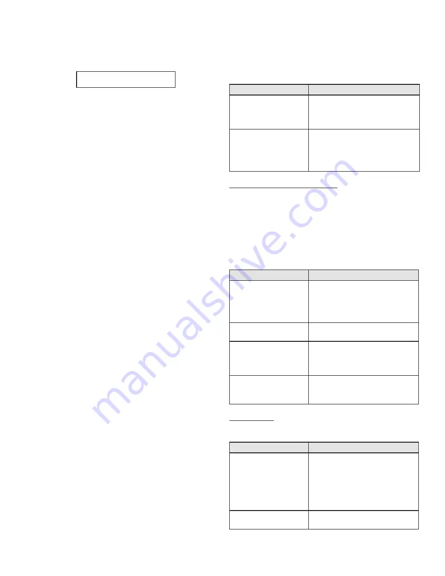
ENTER MENU CODE
000
Screen
Description
ENTER MENU CODE
000
To access the boiler setting program,
press and hold
ENTER
for 4 seconds
until the display shows the screen at
left.
ENTER MENU CODE
600
Use the arrow keys to log in the
Boiler
Menu Access Code - 600
. Press
ENTER
to confirm the code and access the
Boiler Setting Program
navigation
menu.
Table 19 - Boiler Setting Access
Screen
Description
IGNITION DIFF SET
7
o
F
Allows the user to adjust the ignition
differential set point from 1oF to 36
o
F
(Factory Default 7
o
F). Degrees below
set point must be equal to or below
tank differentials.
TANK SETPOINT
120
o
F
Adjusts the tank set point from 59
o
F to
180
o
F (Factory Default 120
o
F).
TANK DIFF SETPOINT
7
o
F
Adjusts the tank differential set point
from 1
o
F to 18
o
F (Factory Default
7
o
F). Degrees below set point where
demand starts.
TEMP DISPLAY C OR F
o
F
Adjusts
the
temperature
measurement in F = Fahrenheit to
C = Celsius (Default is Fahrenheit).
– Resets any lockout error code
– Returns the user to the default display screen.
ENTER
– The ENTER key is used to access parameter
programming mode. To access this mode, hold down the
ENTER key for more than 4 seconds. The readout will change
to:
One of the zeroes will be blinking. Use the
^ v
arrow keys to
change the blinking digit to the correct value. Use the
< >
arrow keys to select the next digit to change and again use the
^ v
keys to change the value. Repeat until the correct code is
entered. Press the
ENTER
key to accept the code entered. If
the code is correct, the readout will change to the appropriate
screen. If the programming code is not accepted, the readout
will continue to display as shown above.
ENTER
is also used to enable a function for editing. After the
user navigates to the desired function, the user holds down
ENTER
for one second. When
ENTER
is released, the function
value will begin to blink. The function can now be changed
using the
^ v
keys. After the new value is displayed, the user
then presses
ENTER
for 1 second to lock the new value of the
function. The value will then stop blinking.
LEFT AND RIGHT ARROW KEYS
–
< >
are used to navigate
between the default display, status display, analog and
cascade displays if they are enabled. The
< >
keys are also used
in programming modes to change between programmable
functions. It is recommended you use the Menu Maps in
the back of this manual and the detailed menu instructions
printed in this section to help in menu navigation.
UP AND DOWN ARROW KEYS
–
^ v
are used to navigate
between the various functions displayed in the menu. After
the function is enabled for editing by pushing the
ENTER
key, the
^ v
keys are used to adjust the function upward or
downward to the desired value.
Table 20 - Boiler Setting Program Navigation
Clock Settings
(
NOTE:
The clock will reset if the boiler is powered off for more
than a week.)
Screen
Description
CLOCK MODE (12/24)
08/28/2009 Fr 9:42A
Changes the clock from 12 hour mode
(8:45 PM) to 24 hour mode (20:45). To
change to 24 hour mode, press
ENTER
.
The letter (A or P) after the time will
blink. Press the up or down arrow key
once and the letter will disappear.
Press
ENTER
to save the new setting.
CLOCK HOUR
08/28/2009 Fr 10:01A
Allows the user to adjust the hour
setting.
Summary of Contents for EP-220 VWH
Page 33: ...LP 551 Rev 3 9 16 33 Figure 24 Cascade Master and FollowerWiring ...
Page 34: ...LP 551 Rev 3 9 16 34 Figure 25 Internal Connection Diagram ...
Page 57: ...LP 551 Rev 3 9 16 57 Figure 30 Combustion System Replacement Parts 220kBTU Model ...
Page 58: ...LP 551 Rev 3 9 16 58 Figure 31 Combustion System Replacement Parts 299 399kBTU Models ...
Page 59: ...LP 551 Rev 3 9 16 59 Figure 32 Replacement Parts All Models ...


