


52
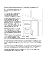
2. Locate and install manual shutoff valves in accordance with state and local requirements.
3. In Canada, the Manual Shutoff must be identified by the installing contractor.
4. It is important to support gas piping as the unit is not designed to structurally support a large amount of weight.
5. Purge all gas lines thoroughly to avoid start up issues with air in the lines.
6. Sealing compound must be approved for gas connections. Care must be taken when applying compound to
prevent blockage or obstruction of gas flow which may affect the operation of the unit.
Failure to apply pipe sealing compound as detailed above could result in substantial property damage, severe
personal injury, or death.
Never use an open flame (match or lighter) to check for gas leaks. Use a soapy solution to test connection.
Failure to use a soapy solution test or check gas connection for leaks can result in substantial property damage,
severe personal injury, or death.
Use two wrenches when tightening gas piping at the boiler: One to prevent the boiler gas line from turning. Failure
to prevent the boiler gas connection from turning could result in damage to the gas line components, substantial
property damage, severe personal injury, or death.
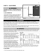
CSA / UL listed flexible gas connections can be used when installing the boiler. Flexible gas connections have
different capacities and must be sized correctly for the connected boiler firing rates. Consult with the flex line
supplier to assure the line size is adequate for the job. Follow local codes for proper installation and service
requirements.
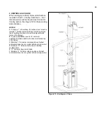
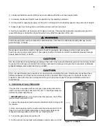
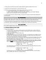
C. CHECK INLET GAS PRESSURE
The gas valve is equipped with an inlet gas pressure tap that can be
used to measure the gas pressure to the unit. To check gas pressure,
perform the steps listed below:
1.
IMPORTANT!
Before you connect to the inlet pressure, shut off the
gas and electrical power to unit.
2. Loosen the pressure tap with a small screwdriver. Refer to Figure 24
for location.
3. Each unit is equipped with a needle valve that will accept a 5/16 ID
hose to connect to a digital manometer or liquid gauge designed to
measure incoming pressure from 0-
35” w.c. See Figure 24.
4. Turn on the gas and power up the unit.
5. Put the unit into manual test mode (details on test mode are in Part
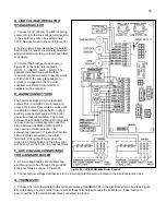
Figure 23
– LP-205-W
Summary of Contents for EL-110
Page 15: ...15 Figure 3 ...
Page 61: ...61 Figure 29 ...
Page 62: ...62 Figure 30 ...
Page 87: ...87 Figure 33 ...
Page 88: ...88 Figure 34 ...
Page 89: ...89 Figure 35 LP 293 A NOTE Parts listed on the following page ...
Page 94: ...94 ...
Page 95: ...95 ...
Page 96: ...96 MAINTENANCE NOTES ...


