


47
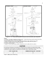
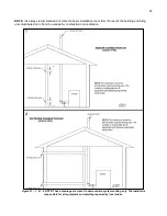
Figure 18
– 1, 18 – 2 Concentric Venting NOTE: Drawing is meant to demonstrate system venting ONLY.
NOTES:
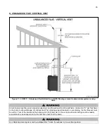
A. For every 1” of overhang, the exhaust vent must be located 1” vertical below overhang (overhang means top of building
structure and not two adjacent walls [corner of building]).
B. Typical installations require 12” minimum separation between bottom of exhaust outlet and top of air intake.
C. Maintain 12” minimum clearance above highest anticipated snow level or grade (whichever is greater).
D. Minimum 12” between vents when installing multiple vents.
E. 12” minimum beyond air intake.
F. Maintain 12” minimum clearance above highest anticipated snow level or grade (whichever is greater).
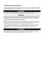
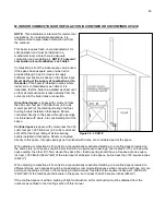
If an existing venting system is converted for use with this boiler, the installer must ensure that the existing
venting system is clean and free from particulate contamination that could damage the boiler. Failure to do so
could result in property damage and boiler failure. Such failure IS NOT covered under warranty.
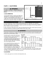
VENT / AIR INLET SIZE
MINIMUM EXISTING VENT / CHASE SIZE
2”
4”
3”
5”
4”
7”
Table 12
– Minimum Vent / Chase Sizing
Summary of Contents for EL-110
Page 15: ...15 Figure 3 ...
Page 61: ...61 Figure 29 ...
Page 62: ...62 Figure 30 ...
Page 87: ...87 Figure 33 ...
Page 88: ...88 Figure 34 ...
Page 89: ...89 Figure 35 LP 293 A NOTE Parts listed on the following page ...
Page 94: ...94 ...
Page 95: ...95 ...
Page 96: ...96 MAINTENANCE NOTES ...