


42
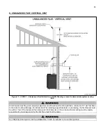
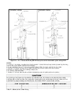
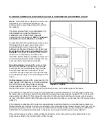
H. SIDEWALL VENTING
NOTE:
Vent piping should be 12” over anticipated maximum snow level.
NOTE:
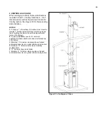
Drawing is meant to demonstrate system venting ONLY.
All vent pipes must be
glued, properly supported, and the exhaust must be pitched a minimum of ¼” per foot back
to the boiler to allow drainage of condensate. When placing support brackets on vent piping, the first bracket must
be within 1 foot of the boiler and the balance at 4 foot intervals on the vent pipe. Boiler venting must be readily
accessible for visual inspection for the first three feet from the boiler.
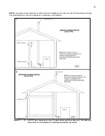
Figure 14
– Sidewall Venting with Tee (Intake) and Coupling (Exhaust) – LP-293-E
Summary of Contents for EL-110
Page 15: ...15 Figure 3 ...
Page 61: ...61 Figure 29 ...
Page 62: ...62 Figure 30 ...
Page 87: ...87 Figure 33 ...
Page 88: ...88 Figure 34 ...
Page 89: ...89 Figure 35 LP 293 A NOTE Parts listed on the following page ...
Page 94: ...94 ...
Page 95: ...95 ...
Page 96: ...96 MAINTENANCE NOTES ...


