


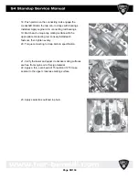
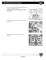
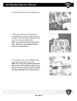


9. Carefully install each piston assembly into the
cylinders. Take care in not scratching the cylinder bore.
10. Install the intake- side chain guide. Tighten fastener to
specification.
11. Carefully rotate engine 180° Do not allow the pistons
to fall out of cylinders.
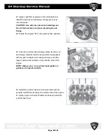
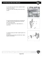
12. Select and install the connecting rod, crankshaft main
bearings, and balance shaft bearings. (Selection is
made using bearing selection process described in this
chapter.)
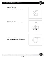
13. Coat all bearings and journals with engine oil. Install
water pump drive gear into crankcase.
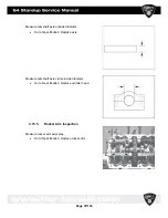
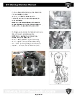
14. Install the chain tensioner guide into the exhaust- side
of the crankcase. Tighten fastener to specification.
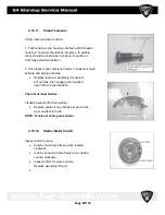
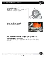
15. Install the balance shaft with the gear facing the front of
the engine.
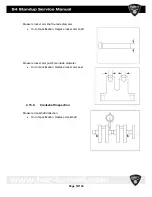
NOTE: Verify bearing surfaces are centered within
journals.
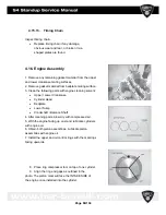
16. Install crankshaft so that the two single- dot alignment
marks located on the balance shaft gear and
crankshaft gear face each other.
NOTE: Verify bearing surfaces are centered within
journals.
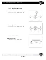
17. Coat bearing surfaces with engine oil.
Page
87/134
Summary of Contents for S4 Standup 2007
Page 1: ...Page 1 134 ...
Page 6: ...Page 6 134 ...
Page 17: ...Page 17 134 ...
Page 39: ...Page 39 134 ...
Page 42: ...Page 42 134 ...
Page 59: ...4 9 Engine case cylinder head assembly Page 59 134 ...
Page 62: ...4 11 Valve assemblies Page 62 134 ...
Page 64: ...4 13 Crankshaft Counter balancer assemblies Page 64 134 ...
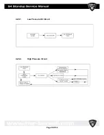
Page 102: ...4 20 1 Low Pressure Oil Circuit 4 20 2 High Pressure Circuit Page 102 134 ...
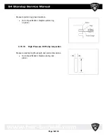
Page 105: ...4 20 6 High Pressure Oil Supply Page 105 134 ...
Page 106: ...Page 106 134 ...
Page 110: ... Please reboot the PC restart the computer Page 110 134 ...
Page 118: ...Start the program SERVICE 1010 HSR exe Page 118 134 ...
Page 130: ...5 5 Electrical System Page 130 134 ...
Page 131: ...Page 131 134 ...


