

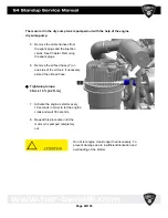
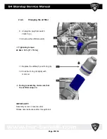

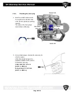


9. Press the rocker downwards with a
24 combination wrench (12).
10. Clamp both valves by pressing in
the sliding piece (13).
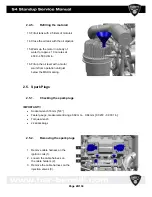
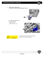
11. Remove the adjustment plate with
the bar magnet.
12. Measure the strength of the
adjustment plate and replace with
an adjustment plate with which the
permissible tolerance is adhered
to.
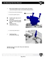
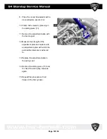
13. Replace the adjustment plate in
the spring seat.
14. Remove the sliding piece (13) and,
to check the valve play, measure
again.
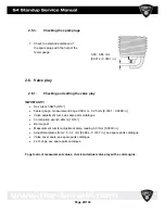
15. Repeat this procedure with all
Valves of the first cylinder.
Page
33/134
Summary of Contents for S4 Standup 2007
Page 1: ...Page 1 134 ...
Page 6: ...Page 6 134 ...
Page 17: ...Page 17 134 ...
Page 39: ...Page 39 134 ...
Page 42: ...Page 42 134 ...
Page 59: ...4 9 Engine case cylinder head assembly Page 59 134 ...
Page 62: ...4 11 Valve assemblies Page 62 134 ...
Page 64: ...4 13 Crankshaft Counter balancer assemblies Page 64 134 ...
Page 102: ...4 20 1 Low Pressure Oil Circuit 4 20 2 High Pressure Circuit Page 102 134 ...
Page 105: ...4 20 6 High Pressure Oil Supply Page 105 134 ...
Page 106: ...Page 106 134 ...
Page 110: ... Please reboot the PC restart the computer Page 110 134 ...
Page 118: ...Start the program SERVICE 1010 HSR exe Page 118 134 ...
Page 130: ...5 5 Electrical System Page 130 134 ...
Page 131: ...Page 131 134 ...


