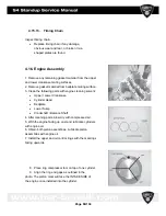

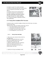
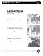


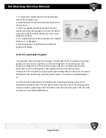


4.18. Thermostat Removal/Installation
NOTE: Coolant will flow out of the cylinder head into the bilge when the outlet rail
elbow is removed. Tilt the bow down to prevent coolant
from escaping outlet rail.
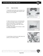
1. Remove the snap ring using a snap ring pliers.
2. Carefully twist and pull the elbow out of the rail.
3. Inspect the o rings. Replace if found worn or damaged.
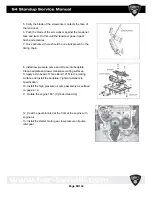
4. Remove and replace thermostat.
5. Insert thermostat with bleed hole up.
6. Reinstall the elbow. Reinstall the snap ring. Verify the
snap ring chamfer faces out when installing.
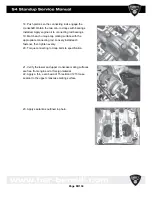
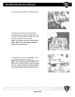
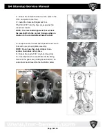
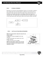
4.19. Water Pump Removal/Installation
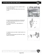
1. The water pump cover can be removed by 4 fasteners
that mount the cover to the front gear cover.
2. Always replace the o ring with new during reassembly.
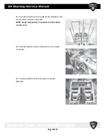
3. The impeller can be removed by
holding the crankshaft.
Stationary while turning the impeller nut
counter- clockwise.
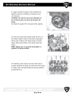
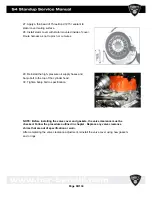
4. Tighten fasteners to specified torque outlined at beginning
of chapter.
Page
100/134
Summary of Contents for S4 Standup 2007
Page 1: ...Page 1 134 ...
Page 6: ...Page 6 134 ...
Page 17: ...Page 17 134 ...
Page 39: ...Page 39 134 ...
Page 42: ...Page 42 134 ...
Page 59: ...4 9 Engine case cylinder head assembly Page 59 134 ...
Page 62: ...4 11 Valve assemblies Page 62 134 ...
Page 64: ...4 13 Crankshaft Counter balancer assemblies Page 64 134 ...
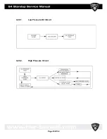
Page 102: ...4 20 1 Low Pressure Oil Circuit 4 20 2 High Pressure Circuit Page 102 134 ...
Page 105: ...4 20 6 High Pressure Oil Supply Page 105 134 ...
Page 106: ...Page 106 134 ...
Page 110: ... Please reboot the PC restart the computer Page 110 134 ...
Page 118: ...Start the program SERVICE 1010 HSR exe Page 118 134 ...
Page 130: ...5 5 Electrical System Page 130 134 ...
Page 131: ...Page 131 134 ...


