


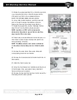
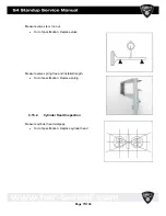
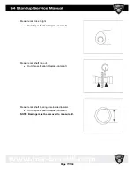


11. Photo of front of engine. Remove the starter motor
drive gear assembly (A) and oil pump drive gear (B).
(
Photo J
)
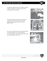
12. Remove lock pin and rotate engine 180_. Remove the
sump cover. (
Photo K
)
NOTE: The sump oil pump is attached to the inside
of the sump cover.
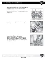
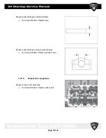
13. Install crankshaft hand crank, PN PW- 46981 into nose
of crankshaft. Tighten lock nut against crankshaft.
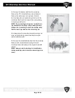
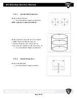
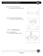
14. The high pressure oil pump is located on the PTO side
of the engine. It is connected to the balance shaft.
Remove the snap ring from the high pressure oil pump
cover. Carefully extract the cap, outer and inner rotors,
timing key and timing rotor from engine. (
Illustration 1)
Page
68/134
Summary of Contents for S4 Standup 2007
Page 1: ...Page 1 134 ...
Page 6: ...Page 6 134 ...
Page 17: ...Page 17 134 ...
Page 39: ...Page 39 134 ...
Page 42: ...Page 42 134 ...
Page 59: ...4 9 Engine case cylinder head assembly Page 59 134 ...
Page 62: ...4 11 Valve assemblies Page 62 134 ...
Page 64: ...4 13 Crankshaft Counter balancer assemblies Page 64 134 ...
Page 102: ...4 20 1 Low Pressure Oil Circuit 4 20 2 High Pressure Circuit Page 102 134 ...
Page 105: ...4 20 6 High Pressure Oil Supply Page 105 134 ...
Page 106: ...Page 106 134 ...
Page 110: ... Please reboot the PC restart the computer Page 110 134 ...
Page 118: ...Start the program SERVICE 1010 HSR exe Page 118 134 ...
Page 130: ...5 5 Electrical System Page 130 134 ...
Page 131: ...Page 131 134 ...


