


HSB Automation GmbH
In Laisen 74
72766 Reutlingen
Germany
Tel. +49 7121 14498-0
Fax +49 7121 14498-10
[email protected]
www.HSB-Automation.de
FM 169 Master A&M Instructions for Gamma type Z..D Rev.01
Distributor:
SCHUNK GmbH & Co. KG
Spann- und Greiftechnik
Bahnhofstr. 106 - 134
74348 Lauffen/Neckar
Deutschland
Tel. +49 7133-103-0
Fax +49 7133-103-2399
[email protected]
www.schunk.com
distributed by
Original
Assembly and
Maintenance
Instructions
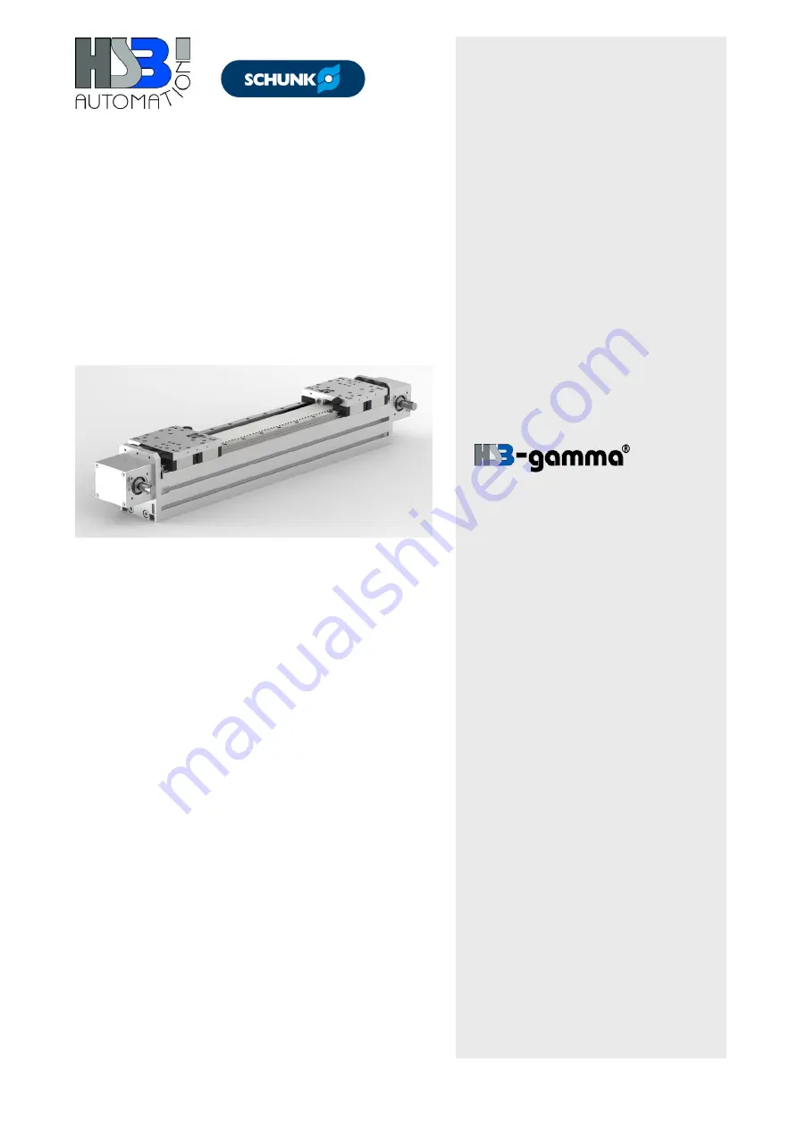
Portal linear unit
Types
Gamma 90-ZSSD
Gamma 120-ZSSD
Gamma 160-ZSSD
Gamma 220-ZSSD
Gamma 280-ZSSD
Summary of Contents for Gamma 120-ZSSD
Page 2: ......