


8
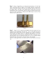
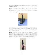
Step 7.
Place a polymer ring over the threaded end of each strut on this layer. Be
sure the polymer ring is seated fully as it was in Step 4. The polymer ring should
sit on the shoulder just below the thread (Picture 7).
Picture 7
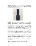
Step 8.
If it is required for the unit you are assembling, refer to steps 1 and 2 to
build another Support/Cross Member subassembly. Ignore any reference to the
threaded studs that the first set of Support Braces had. Only the top layer of braces
will have those studs.
In step 2, finger-tighten the screws attaching the Cross Members to the Support
Brace rather than using the T-wrench. They will be fully tightened later on. If
your SXRC came with brace subassemblies preassembled, the 1/4” - 20 x 3/4” flat
head cap screws must be loosened 1/4 turn before proceeding to Step 9.
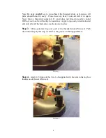
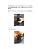
Step 9.
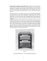
Carefully place the Support/Cross Member subassembly onto the struts
of the SXRC by placing each strut through one hole of the Support Braces. Make
sure the HRS logos on all of the Cross Members face the same direction. Also
make sure that each strut is properly seated into a countersunk hole of the Support
Brace.
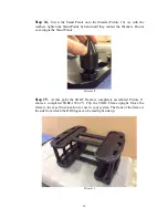
Step 10.
Fully tighten the screws connecting the Cross Members to the Support
Braces. Before tightening screws fully be sure that the Cross Members and
Support Brace are completely perpendicular to each other. Use the ratchet wrench
to tighten the screws about 1/16 to 1/8 of a rotation past snug. This will give you
proper torque on the assembly. After all the screws are tightened, check one more
time to make sure the Struts are still sitting in the counter bores on the backside of
the Support Brace.
Step 11.
Add a polymer ring and oil to each strut as in Steps 3 and 4.


