background image

Bluetooth module

Description

Spare part number

Bluetooth module

537921-001

Bluetooth module cable

602822-001

Before removing the Bluetooth module, follow these steps:

1.

Shut down the computer. If you are unsure whether the computer is off or in Hibernation, turn the
computer on, and then shut it down through the operating system.

2.

Disconnect all external devices connected to the computer.

3.

Disconnect the power from the computer by first unplugging the power cord from the AC outlet
and then unplugging the AC adapter from the computer.

4.

Remove the battery (see 

Battery on page 45

).

5.

Remove the following components:

a.

Hard drive (see 

Hard drive on page 46

)

b.

Optical drive (see 

Optical drive on page 49

)

c.

Keyboard (see 

Keyboard on page 56

)

d.

Top cover (see 

Top cover on page 58

)

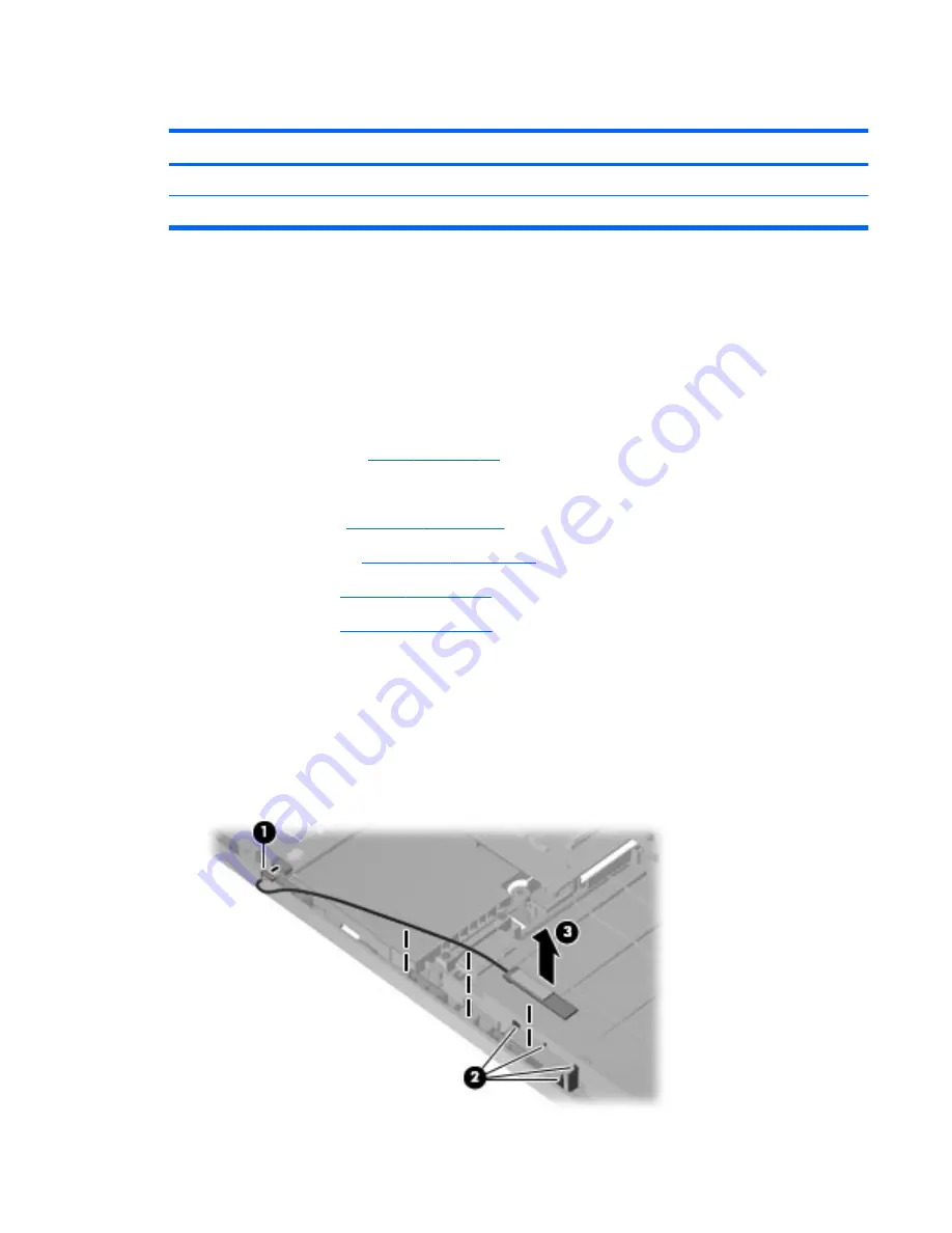
Remove the Bluetooth module:

1.

Position the computer upright with the front toward you.

2.

Disconnect the Bluetooth module cable 

(1)

 from the system board.

3.

Remove the Bluetooth module and cable from the clips in the base enclosure 

(2)

.

4.

Remove the Bluetooth module 

(3)

 from the base enclosure.

Component replacement procedures

67

Summary of Contents for COMPAQ PRESARIO G42

Page 1: ...Guide SUMMARY This guide is a troubleshooting reference used for maintaining and servicing the computer It provides comprehensive information on identifying computer features components and spare parts troubleshooting computer problems and performing computer disassembly procedures ...

Page 2: ...demarks of Microsoft Corporation SD Logo is a trademark of its proprietor The information contained herein is subject to change without notice The only warranties for HP products and services are set forth in the express warranty statements accompanying such products and services Nothing herein should be construed as constituting an additional warranty HP shall not be liable for technical or edito...

Page 3: ...llow another hard surface such as an adjoining optional printer or a soft surface such as pillows or rugs or clothing to block airflow Also do not allow the AC adapter to contact the skin or a soft surface such as pillows or rugs or clothing during operation The computer and the AC adapter comply with the user accessible surface temperature limits defined by the International Standard for Safety o...

Page 4: ...iv Safety warning notice ...

Page 5: ...ntennas 17 Additional hardware components 18 3 Illustrated parts catalog 19 Serial number location 19 Computer major components 20 Display assembly components 27 Plastics Kit 29 Mass storage devices 30 Miscellaneous parts 31 Sequential part number listing 32 4 Removal and replacement procedures 38 Preliminary replacement requirements 38 Tools required 38 Service considerations 38 Plastic parts 38 ...

Page 6: ...67 USB board 69 Power connector cable 71 Display assembly 73 System board 80 Optical drive SATA cable and connector 83 RTC battery 85 Fan heat sink assembly 87 Processor 90 5 Setup Utility 93 Computer Setup in Windows 7 93 Starting Setup Utility 93 Using Setup Utility 94 Changing the language of Setup Utility 94 Navigating and selecting in Setup Utility 94 Displaying system information 95 Restorin...

Page 7: ...stem resource specifications 110 7 Backup and recovery 111 Windows 7 111 Creating recovery discs 112 Backing up your information 113 Using Windows Backup and Restore 114 Using system restore points 115 When to create restore points 115 Create a system restore point 115 Restore to a previous date and time 115 Performing a recovery 115 Recovering from the recovery discs 116 Recovering from the dedic...

Page 8: ...Requirements for specific countries or regions 124 10 Recycling 125 Battery 125 Display 125 Index 131 viii ...

Page 9: ...2 66 GHz SC turbo 4 MB L3 cache i5 540M 2 53 GHz SC turbo 3 MB L3 cache i5 520M 2 4 GHz SC turbo 3 MB L3 cache i5 430M 2 26 GHz turbo to 2 53 GHz 3 MB L3 cache i3 350M 2 26 GHz 3 MB L3 cache i3 330M 2 13 GHz 3 MB L3 cache Intel Pentium DC T4400 2 2 GHz 800 MHz FSB 1 MB L2 cache DC T4300 2 1 GHz 800 MHz FSB 1 MB L2 cache Intel Celeron DC T3100 1 9 GHz 800 MHz FSB 1 MB L2 cache DC T3000 1 8 GHz 800 ...

Page 10: ...530 DC 2 5GHz L2 35W P520 DDR3 1066 Mh AMD Athlon II Processor DC N330 2 3GHz 1M L2 35W P320 DDR3 1066 Mhz AMD Sempron II Processor N120 DDR3 1066 Mhz Chipset Intel HM55 Express Intel GL40 Southbridge ICH9m AMD ATI RS880M Northbridge ATI RS880MD Northbridge Southbridge SB820 Graphics Intel UMA integrated HD Graphics with shared video memory memory size is dynamic change Up to 251 MB on computers w...

Page 11: ...system memory Up to 797 MB for computers with more than 2048 MB system memory Up to 285 MB for computers with more than 1024 MB of system memory ATi Discrete PCI Express x 16 Graphics ATi Mobility Radeon Park LP S3 package ATI Mobility Radeon HD5430 with 512 MB of dedicated video memory 64 MB 16 DDR3 4 pcs 800 MHz Support for BD or HD DVD playback with HD decoder and DX10 support Panel 35 6 cm 14 ...

Page 12: ...1 Hard drives Supports 9 5 mm 6 35 cm 2 5 in hard drives Serial ATA Supports the following drives 640 GB 5400 RPM 500 GB 7200 rpm 320 GB 7200 rpm 250 GB 7200 rpm 160 GB 7200 rpm Optical drives Fixed removal of one screw required SATA 12 7 mm 0 50 in tray load Supports the following drives Blu ray ROM with LightScribe DVD R RW SuperMulti DL Drive Blu ray ROM DVD R RW SuperMulti DL Drive DVD R RW Su...

Page 13: ...ork WLAN options by way of wireless module Intel Centrino Wireless N 1000 802 11b g 1x2 Intel Centrino Wireless N 1000 802 11b g 1x2 plus Broadcom 2070 Bluetooth 2 1 EDR Adapter Atheros AR9285 802 11b g n 1x1 WiFi Adapter Atheros AR9285 802 11b g n 1x1 WiFi Adapter plus Broadcom 2070 Bluetooth 2 1 EDR Adapter Broadcom 4312G 802 11b g WiFi Adapter Broadcom 4312G 802 11b g WiFi Adapter plus Broadcom...

Page 14: ... standard aspect video HDMI v1 3 supporting 1080p with HDCP key Single port configured for either HDMI or 5 in 1 card reader USB 2 0 3 RJ 11 modem with modem option RJ 45 Ethernet with link and activity lights Audio in mono microphone Audio out stereo headphone Smart pin AC adapter plug Keyboard pointing devices 14 0 inch keyboard TouchPad with 2 buttons and 2 way scroll taps enabled as default Po...

Page 15: ...42 UMA Discrete UMA Models 150 199 UMA Models 100 149 Windows 7 Home Premium 32 64 bit Windows 7 Home Basic 32 64 bit Windows 7 Starter 32 bit Free DOS Novell Linux Serviceability End user replaceable parts AC adapter Battery system Hard drive Memory module Optical drive Mini card device 7 ...

Page 16: ...andard features on most computer models To see a list of hardware installed in the computer follow these steps 1 Select Start My Computer 2 In the left pane of the System Tasks window select View system information 3 Select Hardware tab Device Manager You can also add hardware or modify computer configurations using Device Manager 8 Chapter 2 External component identification ...

Page 17: ...the screen 3 Left TouchPad button Functions like the left button on an external mouse 4 Right TouchPad button Functions like the right button on an external mouse There is an unmarked scroll zone inside the right edge of the TouchPad To scroll up and down using the TouchPad vertical scroll zone slide your finger up or down inside the right edge of the TouchPad For more information about TouchPad f...

Page 18: ... 3 Power light On The computer is on Blinking The computer is in the Sleep state Off The computer is off or in Hibernation 4 Wireless light White An integrated wireless device such as a wireless local area network WLAN device and or a Bluetooth device is on Amber All wireless devices are off 10 Chapter 2 External component identification ...

Page 19: ...uter is in the Sleep state briefly press the button to exit Sleep When the computer is in Hibernation briefly press the button to exit Hibernation If the computer has stopped responding and Windows shutdown procedures are ineffective press and hold the power button for at least 5 seconds to turn off the computer To learn more about your power settings select Start Control Panel System and Security...

Page 20: ...when pressed in combination with the esc key 3 Windows logo key Displays the Windows Start menu 4 Windows applications key Displays a shortcut menu for items beneath the pointer 5 Navigation keys Navigate using the Up Down Left and Right arrow keys 6 Action keys Execute frequently used system actions 12 Chapter 2 External component identification ...

Page 21: ...n 1 Internal microphone Records sound 2 Integrated webcam select models only Records audio and video and captures still photographs 3 Integrated webcam light select models only On The integrated webcam is in use Top components 13 ...

Page 22: ...apter power battery light White The computer is connected to external power and the battery is fully charged Blinking white The computer is in the Sleep state Amber A battery is charging 6 Power connector Connects an AC adapter 7 Security cable slot Attaches an optional security cable to the computer NOTE The security cable is designed to act as a deterrent but it may not prevent the computer from...

Page 23: ...y compatible digital or audio component 4 RJ 45 network jack Connects a network cable 5 USB ports 2 Connects optional USB devices 6 Audio in microphone jack Connects an optional computer headset microphone stereo array microphone or monaural microphone 7 Audio out headphone jack Produces sound when connected to optional powered stereo speakers headphones earbuds a headset or television audio 8 Dig...

Page 24: ...y module compartment Contains 2 memory module slots and on select models the wireless LAN WLAN device CAUTION To prevent an unresponsive system replace the wireless module only with a wireless module authorized for use in the computer by the governmental agency that regulates wireless devices in your country or region If you replace the module and then receive a warning message remove the module t...

Page 25: ... outside of the computer NOTE For optimal transmission keep the areas immediately around the antennas free from obstructions To see wireless regulatory notices refer to the section of the Regulatory Safety and Environmental Notices that applies to your country or region These notices are located in Help and Support Wireless antennas 17 ...

Page 26: ... region To use the modem and the modem cable included with select models only outside the country or region in which you purchased the computer you must obtain a country or region specific modem cable adapter included with select models or purchased separately The modem must be connected to an analog telephone line using a 6 pin RJ 11 modem cable included with select models only Jacks for digital ...

Page 27: ...rated parts catalog Serial number location When ordering parts or requesting information provide the computer serial number and model number located in the battery bay of the computer Serial number location 19 ...

Page 28: ... 14 in WXGA BrightView display assembly NOTE See Display assembly components on page 27 for more display assembly internal component spare part information For use with integrated microphone and webcam Presario matte black 592146 001 20 Chapter 3 Illustrated parts catalog ...

Page 29: ...includes cable 600188 001 5 Touchpad button board includes cable 604603 001 6 Thermal module fan and heat assembly includes thermal material For use in models that use UMA graphics subsystem memory and the Intel GL40 chipset 606573 001 For use in models that use Universal Memory Architecture UMA graphics subsystem memory 606609 001 For use in models that use Universal Memory Architecture UMA graph...

Page 30: ... 592809 001 For use in models with HD545V DSC 611554 001 For use in models with HD545V DSC CR 611555 001 For use in models with HD5430 1G DSC 608823 001 For use in models with HD5430 1G DSC HDMI 608824 001 9 Plastics Kit see Plastics Kit on page 29 for more Plastics Kit information 600190 001 9a Hard drive compartment cover 9b Wireless memory module mini card compartment cover 10 RTC battery inclu...

Page 31: ... Liechtenstein Lithuania Luxembourg Macedonia Madagaascar Malawi Malaysia Maldives Mali Malta Marshall Islands Mauritania Mauritius Mexico Micronesia Monaco Mongolia Montenegro Morocco Mozambique Namibia Nauru Nepal Netherlands New Zealand Nicaragua Niger Nigeria Norway Oman Palau Panama Papua New Guinea Paraguay Peru Philippines Poland Portugal Republic of Moldova Romania rwanda Samoa San Marino ...

Page 32: ...apua New Guinea Paraguay Peru The Philippines Poland Portugal Puerto Rico The Republic of Moldova Romania Russia Rwanda Samoa San Marino Sao Tome and Principe Saudi Arabia Senegal Serbia and Montenegro The Seychelles Sierra Leone Singapore Slovakia Slovenia The Solomon Islands Somalia South Africa Spain Sri Lanka St Kitts Nevis St Lucia St Vincent and Gren Suriname Swaziland Sweden Switzerland Tai...

Page 33: ...2 0 GHz 594169 001 Advanced Micro Devices AMD processor DC N830 Tri core 2 1Ghz 1 5M L2 35W 594168 001 15 USB board includes cable 600631 001 16 Modem RJ 11 cable includes RJ 11 connector with modem cable 610791 001 17 Power connector cable includes power connector and cable 600630 001 18 Base enclosure with modem cable and ODD cable For use with HDMI card reader and without modem module biscotti ...

Page 34: ... Layer matte black 600173 001 Blu ray Disc ROM LightScribe with SuperMulti DVD R RW Double Layer biscotti 600174 001 Blu ray Disc ROM LightScribe with SuperMulti DVD R RW Double Layer silver 608121 001 Blu ray Disc ROM LightScribe with SuperMulti DVD R RW Double Layer white 608122 001 DVD RW SuperMulti DL Drive with LightScribe matte black 600171 001 DVD RW SuperMulti DL Drive with LightScribe bis...

Page 35: ... and webcam 592147 001 Presario for use with microphone and webcam 592148 001 2 35 6 cm 14 in high definition Brightview display panel includes display panel cable 592144 001 3 Display hinge cover 592150 001 Display bracket with hinges 600627 001 Display cable kit 592151 001 Display assembly components 27 ...

Page 36: ...cover Presario matte black 592149 001 Presario biscotti 600164 001 HP biscotti 600165 001 HP silver 606157 001 HP white 606158 001 7 Webcam module 600166 001 Display screw kit not illustrated includes screws and screw covers 592152 001 Display rubber display kit not illustrated 595198 001 28 Chapter 3 Illustrated parts catalog ...

Page 37: ...tics Kit Item Description Spare part number Plastics kit 600190 001 1 Hard drive bay cover includes captive screws 2 Wireless memory module mini card compartment cover includes captive screw Plastics Kit 29 ...

Page 38: ...c ROM LightScribe with SuperMulti DVD R RW Double Layer matte black 600173 001 Blu ray Disc ROM LightScribe with SuperMulti DVD R RW Double Layer biscotti 600174 001 Blu ray Disc ROM LightScribe with SuperMulti DVD R RW Double Layer silver 608121 001 Blu ray Disc ROM LightScribe with SuperMulti DVD R RW Double Layer white 608122 001 DVD RW SuperMulti DL Drive with LightScribe matte black 600171 00...

Page 39: ...Argentina 490371 D01 For use in Australia 490371 011 For use in Brazil 490371 202 For use in India 490371 D61 For use in Italy 490371 061 For use in North America 490371 001 For use in South Korea 490371 AD1 For use in Taiwan 490371 AB1 For use in Thailand 490371 201 For use in the People s Republic of China 490371 AA1 For use in the United Kingdom and Singapore 490371 031 Rubber kit 600184 001 Sc...

Page 40: ... m for use in South Korea 490371 D01 Power cord AC 3 pin black 1 83 m for use in Argentina 490371 D61 Power cord AC 3 pin black 1 83 m for use in India 510100 001 Modem module high speed 56K modem for use in all countries and regions except Australia and New Zealand 510100 011 Modem module high speed 56K modem for use in Australia and New Zealand 534419 001 Intel Celeron 900 2 2GHz 537921 001 Blue...

Page 41: ...WiFi adapter for use in Afghanistan Albania Algeria Andorra Angola Antigua and Barbuda Argentina Armenia Aruba Australia Austria Azerbaijan The Bahamas Bahrain Bangladesh Barbados Belgium Belize Benin Bermuda Bhutan Bolivia Bosnia and Herzegovina Botswana Brazil The British Virgin Islands Brunei Bulgaria Burkina Faso Burundi Cameroon Cape Verde the Central African Republic Chad Chile China Colombi...

Page 42: ...Advanced Micro Devices AMD P320 DDR3 1066 Mhz 594166 001 ProcessorAdvanced Micro Devices AMD N620 DDR3 1333 Mhz 594187 001 Processor Intel Arrandale 520M 2 4 GHz 594167 001 Processor Advanced Micro Devices AMD DC P820 Tri Core 1 8Ghz 1 5M L2 25W 594188 001 Processor Intel Arrandale 540M 2 53 GHz 594168 001 Processor Advanced Micro Devices AMD DC N830 Tri core 2 1Ghz 1 5M L2 35W 595181 001 System b...

Page 43: ...00163 001 35 6 cm 14 in WXGA Brightview display assembly for use with integrated microphone and webcam HP biscotti 600164 001 Display back cover Presario biscotti 600165 001 Display back cover HP biscotti 600166 001 Webcam module 600167 001 Hard disk drive 160 GB 7200 RPM 600169 001 Hard disk drive 320 GB 7200 RPM 600170 001 Hard disk drive 500 GB 7200 RPM 600171 001 Optical drive DVD RW SuperMult...

Page 44: ...screws and hard drive bracket 600370 001 SPS WLAN BGN BT HMC Combo Matador 600627 001 Display bracket with hinges 600630 001 Power connector with cable 600631 001 USB board with cable 602745 001 RTC battery 602822 001 Bluetooth cable 602992 001 SPS WLAN BGN 1x1 BT HMC Combo Rashi 604603 001 Touchpad board includes cable 605140 001 System board includes replacement thermal material for use in model...

Page 45: ... reader and without modem white 610791 001 Optical drive cable included in the cable kit 610791 001 Modem RJ 11 cable with modem connector included in the cable kit 610791 001 Hard drive cable adaptor included in the cable kit 613152 001 65 W Smart AC adapter 611554 001 For use in systems boards with HD545V DSC 611555 001 For use in system boards with HD545V DSC CR 613153 001 90 W AC adapter with ...

Page 46: ...e some of the considerations that you must keep in mind during disassembly and assembly procedures NOTE As you remove each subassembly from the computer place the subassembly and all accompanying screws away from the work area to prevent damage Plastic parts Using excessive force during disassembly and reassembly can damage plastic parts Use care when handling the plastic parts Apply pressure only...

Page 47: ... inserting a hard drive shut down the computer If you are unsure whether the computer is off or in Hibernation turn the computer on and then shut it down through the operating system Before handling a drive be sure that you are discharged of static electricity While handling a drive avoid touching the connector Before removing a diskette drive or optical drive be sure that a diskette or disc is no...

Page 48: ...ep components in their electrostatic safe containers until you are ready to install them Use nonmagnetic tools Before touching an electronic component discharge static electricity by using the guidelines described in this section Avoid touching pins leads and circuitry Handle electronic components as little as possible If you remove a component place it in an electrostatic safe container The follo...

Page 49: ...nd and that proper materials are selected to avoid static charging When grounding is not possible use an ionizer to dissipate electric charges Workstation guidelines Follow these grounding workstation guidelines Cover the workstation with approved static shielding material Use a wrist strap connected to a properly grounded work surface and use properly grounded tools and equipment Use conductive f...

Page 50: ...tween the operator and ground To be effective the conductive strips must be worn in contact with the skin The following grounding equipment is recommended to prevent electrostatic damage Antistatic tape Antistatic smocks aprons and sleeve protectors Conductive bins and other assembly or soldering aids Nonconductive foam Conductive tabletop workstations with ground cords of one megohm resistance St...

Page 51: ...ing the computer Make special note of each screw size and location during removal and replacement Serial number The serial number label located in the battery bay of the computer provides important information that you may need when contacting technical support 1 Product name 4 Warranty period 2 Serial number 5 Model description select models 3 Product number Component replacement procedures 43 ...

Page 52: ...ption Spare part number Rubber Feet Kit 600184 001 The computer feet are adhesive backed rubber pads The feet attach to the base enclosure in the locations illustrated below 44 Chapter 4 Removal and replacement procedures ...

Page 53: ...er 3 Disconnect the power from the computer by first unplugging the power cord from the AC outlet and then unplugging the AC adapter from the computer Remove the battery 1 Turn the computer upside down on a flat surface 2 Slide the battery release latch 1 to release the battery 3 Pivot the battery 2 upward and lift it out of the computer 3 To insert the battery insert the rear edge of the battery ...

Page 54: ... 1 Shut down the computer If you are unsure whether the computer is off or in Hibernation turn the computer on and then shut it down through the operating system 2 Disconnect all external devices connected to the computer 3 Disconnect the power from the computer by first unplugging the power cord from the AC outlet and then unplugging the AC adapter from the computer 4 Remove the battery see Batte...

Page 55: ... hard drive cover is included in the plastics kit spare part number 600190 001 4 Remove the three Phillips PM2 5 4 0 screws 1 that secure the hard drive to the computer 5 Use the hard drive bracket to lift the hard drive out 2 of the hard drive compartment Component replacement procedures 47 ...

Page 56: ...8 If it is necessary to replace the hard drive bracket remove the four Phillips PM3 0 3 0 screws 1 that secure the hard drive bracket to the hard drive 9 Lift the bracket 2 straight up Reverse this procedure to install the hard drive 48 Chapter 4 Removal and replacement procedures ...

Page 57: ... removing the optical drive follow these steps 1 Shut down the computer If you are unsure whether the computer is off or in Hibernation turn the computer on and then shut it down through the operating system 2 Disconnect all external devices connected to the computer 3 Disconnect the power from the computer by first unplugging the power cord from the AC outlet and then unplugging the AC adapter fr...

Page 58: ... drive with the optical drive bracket toward you 6 Remove the two Phillips PM2 0 3 0 screws 1 that secure the optical drive bracket to the optical drive 7 Remove the optical drive bracket 2 Reverse the above procedure to reassemble and install the optical drive 50 Chapter 4 Removal and replacement procedures ...

Page 59: ... Yemen Zambia and Zimbabwe 580101 002 Intel Centrino Wireless N 1000 802 11b g n 1x2 593530 001 Broadcom 4312G 802 11b g WiFi Adapter for use in Canada Cayman Islands Guam Puerto Rico the United States and the U S Virgin Islands 582562 001 Broadcom 4312G 802 11b g WiFi Adapter for use in Afghanistan Albania Algeria Andorra Angola Antigua and Barbuda Argentina Armenia Aruba Australia Austria Azerba...

Page 60: ...let and then unplugging the AC adapter from the computer 4 Remove the battery see Battery on page 45 5 Remove the hard drive cover see Hard drive on page 46 Remove the WLAN module 1 Turn the computer upside down with the front toward you 2 Loosen the 2 Phillips PM2 5 5 0 captive screws 1 that secure the mini card compartment cover 3 Lift the cover off the computer 2 The mini card compartment cover...

Page 61: ... agency that regulates wireless devices in your country or region If you replace the module and then receive a warning message remove the module to restore computer functionality and then contact technical support through Help and Support NOTE WLAN modules are designed with a notch 4 to prevent incorrect insertion into the WLAN module slot Reverse this procedure to install a WLAN module Component ...

Page 62: ...the operating system 2 Disconnect all external devices connected to the computer 3 Disconnect the power from the computer by first unplugging the power cord from the AC outlet and then unplugging the AC adapter from the computer 4 Remove the battery see Battery on page 45 Remove the memory module 1 Turn the computer upside down with the front toward you 2 Loosen the two Phillips PM2 5 5 0 captive ...

Page 63: ...d the retaining tabs 1 on each side of the memory module slot to release the memory module The edge of the module opposite the slot rises away from the computer 5 Remove the module 2 by pulling it away from the slot at an angle NOTE Memory modules are designed with a notch 3 to prevent incorrect insertion into the memory module slot Reverse this procedure to install a memory module Component repla...

Page 64: ...s off or in Hibernation turn the computer on and then shut it down through the operating system 2 Disconnect all external devices connected to the computer 3 Disconnect the power from the computer by first unplugging the power cord from the AC outlet and then unplugging the AC adapter from the computer 4 Remove the battery see Battery on page 45 5 Remove the hard drive see Hard drive on page 46 6 ...

Page 65: ... keyboard from the tabs on the top cover 1 6 Slide the top edge of the keyboard back 2 until it rests against the display 7 Release the zero insertion force ZIF connector 1 to which the keyboard cable is attached and disconnect the keyboard cable 2 from the system board 8 Remove the keyboard Reverse this procedure to install the keyboard Component replacement procedures 57 ...

Page 66: ...it down through the operating system 2 Disconnect all external devices connected to the computer 3 Disconnect the power from the computer by first unplugging the power cord from the AC outlet and then unplugging the AC adapter from the computer 4 Remove the following components a Battery see Battery on page 45 b Optical drive see Optical drive on page 49 c Keyboard see Keyboard on page 56 Remove t...

Page 67: ...e up with the front toward you 5 Open the computer as far as possible 6 Release the ZIF connector to which the touchpad 1 is connected and disconnect the cable from the system board 7 Release the ZIF connector to which the touchpad button board cable 2 is connected and disconnect the cable from the system board 8 Disconnect the speaker cable 3 from the system board Component replacement procedures...

Page 68: ... cable from the system board 10 Remove the Phillips PM2 5 6 5 screw 1 from the top cover disengage the rear edge of the top cover 2 from the base enclosure and then remove the cover from the computer 3 Reverse this procedure to install the switch cover 60 Chapter 4 Removal and replacement procedures ...

Page 69: ...ugging the power cord from the AC outlet and then unplugging the AC adapter from the computer 4 Remove the battery see Battery on page 45 5 Remove the following components a Optical drive see Optical drive on page 49 b Keyboard see Keyboard on page 56 c Top cover see Top cover on page 58 Remove the speaker assembly 1 Turn the top cover upside down 2 Remove the two Phillips PM2 5 4 0 screws 1 that ...

Page 70: ...r by first unplugging the power cord from the AC outlet and then unplugging the AC adapter from the computer 4 Remove the battery see Battery on page 45 5 Remove the following components a Hard drive see Hard drive on page 46 b Optical drive see Optical drive on page 49 c Keyboard see Keyboard on page 56 d Top cover see Top cover on page 58 Remove the power button board 1 Turn the top cover upside...

Page 71: ...t unplugging the power cord from the AC outlet and then unplugging the AC adapter from the computer 4 Remove the battery see Battery on page 45 5 Remove the following components a Hard drive see Hard drive on page 46 b Optical drive see Optical drive on page 49 c Keyboard see Keyboard on page 56 d Top cover see Top cover on page 58 Remove the TouchPad button board 1 Turn the top cover upside down ...

Page 72: ...Reverse the above procedure to reassemble and install the TouchPad button board 64 Chapter 4 Removal and replacement procedures ...

Page 73: ...Disconnect all external devices connected to the computer 3 Disconnect the power from the computer by first unplugging the power cord from the AC outlet and then unplugging the AC adapter from the computer 4 Remove the battery see Battery on page 45 5 Remove the following components a Hard drive see Hard drive on page 46 b Optical drive see Optical drive on page 49 c Keyboard see Keyboard on page ...

Page 74: ...t it from the system board 5 Remove the modem module Reverse the above procedure to install the modem module and be sure that the connector on the bottom of the modem module connects firmly into the system board 66 Chapter 4 Removal and replacement procedures ...

Page 75: ...ing the power cord from the AC outlet and then unplugging the AC adapter from the computer 4 Remove the battery see Battery on page 45 5 Remove the following components a Hard drive see Hard drive on page 46 b Optical drive see Optical drive on page 49 c Keyboard see Keyboard on page 56 d Top cover see Top cover on page 58 Remove the Bluetooth module 1 Position the computer upright with the front ...

Page 76: ...Reverse the above procedure to install the Bluetooth module 68 Chapter 4 Removal and replacement procedures ...

Page 77: ...e AC outlet and then unplugging the AC adapter from the computer 4 Remove the battery see Battery on page 45 5 Remove the following components a Hard drive see Hard drive on page 46 b Optical drive see Optical drive on page 49 c Keyboard see Keyboard on page 56 d Top cover see Top cover on page 58 Remove the USB board 1 Position the computer upright with the right side toward you 2 Disconnect the ...

Page 78: ...Reverse this procedure to install the USB board 70 Chapter 4 Removal and replacement procedures ...

Page 79: ...rst unplugging the power cord from the AC outlet and then unplugging the AC adapter from the computer 4 Remove the battery see Battery on page 45 5 Remove the following components a Hard drive see Hard drive on page 46 b Optical drive see Optical drive on page 49 c Keyboard see Keyboard on page 56 d Top cover see Top cover on page 58 Remove the power connector cable 1 Turn the computer upright wit...

Page 80: ...Reverse this procedure to install the power connector cable 72 Chapter 4 Removal and replacement procedures ...

Page 81: ...off or in Hibernation turn the computer on and then shut it down through the operating system 2 Disconnect all external devices connected to the computer 3 Disconnect the power from the computer by first unplugging the power cord from the AC outlet and then unplugging the AC adapter from the computer 4 Remove the battery see Battery on page 45 5 Disconnect the wireless antenna cables from the WLAN...

Page 82: ...play screws in the following steps Failure to support the display assembly can result in damage to the assembly and other components 7 Remove the four black Phillips PM2 5 6 5 screws 1 that secure the display assembly to the computer 8 Remove the display assembly 2 74 Chapter 4 Removal and replacement procedures ...

Page 83: ...ylar screw covers on the display bezel bottom edge 2 Two Phillips PM2 5 4 0 screws 10 Flex the inside edge of the top 1 the left and right sides 2 and the bottom 3 of the display bezel until the bezel disengages from the display back cover 11 Remove the display bezel 4 The display bezel is available using spare part number 592147 001 for HP computers and 592148 001 for Presario computers Component...

Page 84: ...s 1 that secure the display panel to the display enclosure and then lift the panel from the enclosure 2 The display panel is available using the spare part number 592144 001 14 If it is necessary to replace the display cable follow these steps a Turn the display panel upside down in front of you b Peel back the tape that secures the cable to the display 1 c Unplug the cable from the display 2 d Re...

Page 85: ...he display hinges 2 from the display The display bracket and hinge set is available using spare part number 600627 001 17 If it is necessary to replace the wireless antennas and cables remove the adhesive strip 1 that secures each antenna to the display back cover 18 Detach the wireless antenna 2 from the display back cover 19 Remove the antenna cables from the clips 3 built into the display enclo...

Page 86: ... kit spare part number 592151 001 21 If it is necessary to remove the webcam cable remove the cable from the adhesive strips 1 along the cable path on the display back cover and then remove the webcam cable 2 The webcam cable is included in the display cable kit spare part number 592151 001 78 Chapter 4 Removal and replacement procedures ...

Page 87: ...isplay back cover remove the microphone from the clips on the display back cover 2 and then remove the microphone and microphone cable 3 The microphone and cable is included in the display cable kit spare part number 592151 001 Reverse this procedure to reassemble and install the display assembly Component replacement procedures 79 ...

Page 88: ...aphics subsystem HM55 HD5430 1G 608823 001 For use in models with discrete graphics subsystem HDMI HD5430 1G 608824 001 For use in models with discrete graphics subsystem with HM55 HD545V 615577 001 For use in models with discrete graphics subsystem with HM55 HDMI HD545V 615578 001 When replacing the system board be sure that the following components are removed from the defective system board and...

Page 89: ...mbly on page 73 h Top cover see Top cover on page 58 Remove the following cables from the system board if still connected Power connector cable see Power connector cable on page 71 Bluetooth cable see Bluetooth module on page 67 USB board cable see USB board on page 69 1 Turn the computer upright with the right side toward you 2 Remove the three Phillips PM2 5 3 0 screws that secure the system boa...

Page 90: ...ove the modem module cable 2 from the routing channel built into the base enclosure The modem module cable is available using spare part number 610791 001 When replacing the system board be sure that the following components are removed from the defective system board and installed on the replacement system board Fan heat sink assembly see Fan heat sink assembly on page 87 Processor see Processor ...

Page 91: ...he power cord from the AC outlet and then unplugging the AC adapter from the computer 4 Remove the battery see Battery on page 45 5 Remove the following components a Hard drive see Hard drive on page 46 b WLAN see WLAN module on page 51 c Optical drive see Optical drive on page 49 d Keyboard see Keyboard on page 56 e Top cover see Top cover on page 58 f Speaker assembly see Speaker assembly on pag...

Page 92: ...2 Release the cable from the clips on the base enclosure 2 and then remove the cable 3 84 Chapter 4 Removal and replacement procedures ...

Page 93: ...tlet and then unplugging the AC adapter from the computer 4 Remove the battery see Battery on page 45 5 Remove the following components a Hard drive see Hard drive on page 46 b WLAN see WLAN module on page 51 c Optical drive see Optical drive on page 49 d Keyboard see Keyboard on page 56 e Top cover see Top cover on page 58 f Speaker assembly see Speaker assembly on page 61 g Display assembly see ...

Page 94: ...3 Remove the RTC battery 2 Reverse this procedure to install the RTC battery 86 Chapter 4 Removal and replacement procedures ...

Page 95: ...n The fan is controlled by a temperature sensor and is designed to turn on automatically when high temperature conditions exist These conditions are affected by high external temperatures system power consumption power management battery conservation configurations battery fast charging and software requirements Exhaust air is displaced through the ventilation grill located on the left side of the...

Page 96: ...ink assembly from side to side to detach the assembly 4 Remove the fan heat sink assembly 3 The thermal material must be thoroughly cleaned from the surface of the fan heat sink assembly 1 3 and the processor 2 and video components 4 each time the fan heat sink assembly is removed Thermal pads and thermal paste must be installed on all surfaces before the fan heat sink assembly is reinstalled NOTE...

Page 97: ...n heat sink assembly is removed Thermal pads and thermal paste must be installed on all surfaces before the fan heat sink assembly is reinstalled The following illustration shows the locations for thermal material on systems with UMA graphics subsystems Reverse this procedure to install the fan heat sink assembly Component replacement procedures 89 ...

Page 98: ...100 1 9 GHz 572925 001 Processor Intel Core 2 Duo Mobile processor T4500 2 3 GHz 591880 001 Intel Core 2 Duo Mobile processor T3300 2 0 GHz 592399 001 Processor Advanced Micro Devices AMD P320 DDR3 1066 Mhz 594165 001 Advanced Micro Devices AMD processor N120 DDR3 1066 Mhz 594171 001 Advanced Micro Devices AMD processor P520 DDR3 1066 Mhz 594173 001 Advanced Micro Devices AMD processor DC N330 2 3...

Page 99: ...m the computer 4 Remove the battery see Battery on page 45 5 Remove the following components a Hard drive see Hard drive on page 46 b Optical drive see Optical drive on page 49 c Keyboard see Keyboard on page 56 d Top cover see Top cover on page 58 e Speaker assembly see Speaker assembly on page 61 f Display assembly see Display assembly on page 73 g System board see System board on page 80 h Fan ...

Page 100: ... it NOTE The gold triangle 3 on the processor must be aligned with the triangle icon 4 embossed on the processor socket when you install the processor Reverse this procedure to install the processor 92 Chapter 4 Removal and replacement procedures ...

Page 101: ... your Windows operating system is not working The utility reports information about the computer and provides settings for startup security and other preferences To start Setup Utility Open Setup Utility by turning on or restarting the computer While the Press the ESC key for Startup Menu message is displayed in the lower left corner of the screen press f10 or 1 Open Setup Utility by turning on or...

Page 102: ...uration Language and then press enter 3 Use the arrow keys to select a language and then press enter 4 When a confirmation prompt with your language selected is displayed press enter 5 To save your change and exit Setup Utility use the arrow keys to select Exit Exit Saving Changes and then press enter Your change goes into effect immediately Navigating and selecting in Setup Utility Because Setup ...

Page 103: ...ault settings in Setup Utility The following procedure explains how to restore Setup Utility default settings If Setup Utility is not already running begin at step 1 If Setup Utility is already running begin at step 2 1 Open Setup Utility by turning on or restarting the computer While the Press the ESC key for Startup Menu message is displayed in the lower left corner of the screen press f10 or Op...

Page 104: ...s and then press enter After either choice the computer restarts in Windows Setup Utility menus The menu tables in this section provide an overview of Setup Utility options NOTE Some of the Setup Utility menu items listed in this chapter may not be supported by your computer Main menu Select To do this System information View and change the system time and date View identification information abou...

Page 105: ...led the computer fan will always be on Action Keys Mode Enable disable Action Keys Mode Boot Options Set the following boot options POST hotkey delay sec Set the delay for the f1 f2 f9 f10 f11 and f12 functions of Setup Utility in intervals of 5 seconds each 0 5 10 15 20 CD ROM Boot Enable disable boot from CD ROM Floppy Boot Enable disable boot from diskette Internal Network Adapter Boot Enable d...

Page 106: ...elect To do this Secondary Hard Disk Self Test select models only Run a comprehensive self test on a secondary hard drive Memory Test Run a diagnostic test on the system memory 98 Chapter 5 Setup Utility ...

Page 107: ...the File Security Diagnostics and System Configuration menus 1 Open Computer Setup by turning on or restarting the computer and then pressing f10 while the F10 ROM Based Setup message is displayed in the lower left corner of the screen Because Computer Setup is not operating system based it does not support the TouchPad Navigation and selection are by keystroke To choose a menu or a menu item use ...

Page 108: ...essage is displayed in the lower left corner of the screen 2 Use the arrow keys to select File Restore Defaults and then press enter 3 When the confirmation dialog box opens press f10 4 To save your preferences and exit Computer Setup use the arrow keys to select File Save Changes And Exit Then follow the instructions on the screen Your preferences go into effect when the computer restarts NOTE Yo...

Page 109: ...ssor cache and memory size and system ROM Restore Defaults Replace the configuration settings in Computer Setup with the original factory settings Password settings and security settings are not changed when you restore the factory settings Ignore Changes And Exit Cancel any changes entered during the current session Then exit and restart the computer Save Changes And Exit Save any changes entered...

Page 110: ...turning on not restarting the computer System IDs Enter a user defined computer asset tracking number and ownership tag Disk Sanitizer Run Disk Sanitizer to destroy all existing data on the primary hard drive The following options are available Fast Runs the Disk Sanitizer erase cycle once Optimum Runs the Disk Sanitizer erase cycle 3 times Custom Allows you to select the desired number of Disk Sa...

Page 111: ... 4th boot device Notebook hard drive 5th boot device USB hard disk 6th boot device Network controller Device Configurations Swap the functions of the fn key and left ctrl key Enable disable USB legacy support When enabled USB legacy support allows the following Use of a USB keyboard in Computer Setup even when a your operating system is not running Startup from bootable USB devices including a har...

Page 112: ...e disable embedded Bluetooth Device Radio Enable disable Network Interface Controller NIC Enable disable LAN WLAN Switching Enable disable Wake on LAN Enable disable the integrated camera webcam Port options Enable disable USB port Enable disable ExpressCard slot 104 Chapter 5 Setup Utility ...

Page 113: ...t writing to optical disc 0 C to 35 C 32 F to 95 F Operating writing to optical disc 5 C to 35 C 41 F to 95 F Nonoperating 20 C to 60 C 4 F to 140 F Relative humidity Operating 10 to 90 Nonoperating 5 to 95 Maximum altitude unpressurized Operating 15 m to 3 048 m 50 ft to 10 000 ft Nonoperating 15 m to 12 192 m 50 ft to 40 000 ft NOTE Applicable product safety standards specify thermal limits for ...

Page 114: ... colors Up to 16 8 million Contrast ratio 300 1 typical Brightness 200 nits typical Pixel resolution Pitch 0 259 0 259 mm Format 1280 800 HD 1366 768 Configuration RGB vertical stripe Backlight LED Character display 80 25 Total power consumption 4 0 W Viewing angle 40 horizontal 120 40 vertical typical 106 Chapter 6 Specifications ...

Page 115: ...g Single track 1 0 ms 1 5 ms 2 0 ms 1 5 ms Average 14 0 ms 12 0 ms 12 0 ms 11 0 ms Maximum 22 0 ms 22 0 ms 22 0 ms 22 0 ms Logical blocks 976 773 168 625 142 448 488 397 168 312 581 808 Disc rotational speed 7200 rpm 7200 rpm 7200 rpm 7200 rpm Operating temperature 5 C to 55 C 41 F to 131 F 1 GB 1 billion bytes when referring to hard drive storage capacity Actual accessible capacity is less Actual...

Page 116: ...D 10 DVD 18 DVD R DVD RW DVD R DVD RW DVD RAM Write CD R and CD RW DVD R DVD RW DVD R DVD RW DVD RAM Random access time DVD 230 ms CD 175 ms Cache buffer 2 MB Data transfer rate 24X CD ROM 3 600 KB sec 8X DVD ROM 10 800 KB sec 24X CD R 3 600 KB sec 16X CD RW 2 400 KB sec 8X DVD R 10 800 KB sec 4X DVD RW 5 400 KB sec 8X DVD R 10 800 KB sec 4X DVD RW 5 400 KB sec 2 4X DVD R 9 2 700 KB sec 5X DVD RAM...

Page 117: ... 2 DVD R DVD R CD R and CD ROM Random access time BD 230 ms DVD 180 ms CD 180 ms Cache buffer 8 MB Data transfer rate 24X CD ROM 3 600 KB sec 8X DVD ROM 10 800 KB sec 4X BD 18 000 KB sec 24X CD R 3 600 KB sec 16X CD RW 2 400 KB sec 8X DVD R 10 800 KB sec 4X DVD RW 5 400 KB sec 8X DVD R 10 800 KB sec 4X DVD RW 5 400 KB sec 2 4X DVD R 9 2 700 KB sec 5X DVD RAM 6 750 KB sec 1X BD ROM 4 500 KB sec 1X ...

Page 118: ...er to malfunction or become inoperable Only users who have expert knowledge of computer hardware and hardware configurations should change resource settings To view resource settings in Windows 7 and Windows Vista 1 Select Start Computer 2 Click System properties near the top of the Computer folder 3 On the left click Device Manager 4 On the View menu click one of the following Resources by type R...

Page 119: ...ram or driver without performing a full system recovery Performing a full system recovery Recovery Manager software feature With Recovery Manager you can recover your full factory image if you experience system failure or instability Recovery Manager works from a dedicated recovery partition select models only on the hard drive or from recovery discs you create NOTE Computers with a solid state dr...

Page 120: ...hard drive must be connected to a USB port on the computer not to a USB port on an external device such as a hub You will need high quality DVD R DVD R BD R writable Blu ray or CD R discs All these discs are purchased separately DVDs and BDs have a much higher capacity than CDs If you use CDs up to 20 discs may be required whereas only a few DVDs or BDs are required NOTE Read write discs such as C...

Page 121: ...g a screen shot of your settings The screen shot can be a time saver if you have to reset your preferences To copy the screen and paste it into a word processing document follow these steps 1 Display the screen 2 Copy the screen To copy only the active window press alt prt sc To copy the entire screen press prt sc 3 Open a word processing document and then select Edit Paste 4 Save the document You...

Page 122: ...nd the speed of the computer 1 Select Start All Programs Maintenance Backup and Restore 2 Follow the on screen instructions to set up and create a backup NOTE Windows includes the User Account Control feature to improve the security of your computer You may be prompted for your permission or password for tasks such as installing software running utilities or changing Windows settings Refer to Help...

Page 123: ...ge your mind you can reverse the restoration Create a system restore point 1 Select Start Control Panel System and Security System 2 In the left pane click System Protection 3 Click the System Protection tab 4 Under Protection Settings select the disk for which you want to create a restore point 5 Click Create 6 Follow the on screen instructions Restore to a previous date and time To revert to a r...

Page 124: ... recovery disc into the optical drive and restart the computer 3 Follow the on screen instructions Recovering from the dedicated recovery partition select models only NOTE Computers with an SSD may not have a recovery partition If the computer does not have a recovery partition you will not be able to recover using this procedure Recovery discs have been included for computers that do not have a p...

Page 125: ...ating system and HP programs and drivers that were installed at the factory Software drivers and updates not installed by HP must be manually reinstalled Personal files must be restored from a backup To recover the original hard drive image using f11 follow these steps 1 If possible back up all personal files 2 Restart the computer and then press f11 while the Press F11 for recovery message is dis...

Page 126: ...assignments Audio out headphone Pin Signal 1 Audio out left channel 2 Audio out right channel 3 Ground Audio in microphone Pin Signal 1 Audio signal in 2 Audio signal in 3 Ground 118 Chapter 8 Connector pin assignments ...

Page 127: ...d analog 2 Green analog 3 Blue analog 4 Not connected 5 Ground 6 Ground analog 7 Ground analog 8 Ground analog 9 5 VDC 10 Ground 11 Monitor detect 12 DDC 2B data 13 Horizontal sync 14 Vertical sync 15 DDC 2B clock External monitor 119 ...

Page 128: ...modem Pin Signal 1 Unused 2 Tip 3 Ring 4 Unused 5 Unused 6 Unused RJ 45 network Pin Signal 1 Transmit 2 Transmit 3 Receive 4 Unused 5 Unused 6 Receive 7 Unused 8 Unused 120 Chapter 8 Connector pin assignments ...

Page 129: ... data 2 4 TMDS data 1 5 TMDS data 1shield 6 TMDS data 1 7 TMDS data 0 8 TMDS data 0 shield 9 TMDS data 0 10 TMDS clock 11 TMDS clock shield 12 TMDS clock 13 CEC 14 No connect 15 DDC clock 16 DDC data 17 Ground 18 5V power 19 Hot plug detect 20 Shell HDMI 121 ...

Page 130: ...Universal Serial Bus Pin Signal 1 5 VDC 2 Data 3 Data 4 Ground 122 Chapter 8 Connector pin assignments ...

Page 131: ...ents listed below are applicable to all countries or regions The length of the power cord set must be at least 1 5 m 5 0 ft and no more than 2 0 m 6 5 ft All power cord sets must be approved by an acceptable accredited agency responsible for evaluation in the country or region where the power cord set will be used The power cord sets must have a minimum current capacity of 10 amps and a nominal vo...

Page 132: ...g must be a two pole grounding type with a NEMA 5 15P 15 A 125 V or NEMA 6 15P 15 A 250 V configuration 3 The appliance coupler flexible cord and wall plug must bear a T mark and registration number in accordance with the Japanese Dentori Law The flexible cord must be Type VCT or VCTF 3 conductor 1 00 mm conductor size The wall plug must be a two pole grounding type with a Japanese Industrial Stan...

Page 133: ...handle them carefully NOTE Materials Disposal This HP product contains mercury in the backlight in the display assembly that might require special handling at end of life Disposal of mercury may be regulated because of environmental considerations For disposal or recycling information contact your local authorities or see the Electronic Industries Alliance EIA Web site at http www eiae org This se...

Page 134: ... 1 and screws 2 that secure the display bezel to the display assembly 2 Lift up and out on the left and right inside edges 1 and the top and bottom inside edges 2 of the display bezel until the bezel disengages from the display assembly 3 Remove the display bezel 3 126 Chapter 10 Recycling ...

Page 135: ...ssembly to the display enclosure 6 Remove the display panel assembly 2 from the display enclosure 7 Turn the display panel assembly upside down 8 Remove all screws that secure the display panel frame to the display panel 9 Use a sharp edged tool to cut the tape 1 that secures the sides of the display panel to the display panel frame Display 127 ...

Page 136: ...splay panel 11 Remove the screws 1 that secure the backlight cover to the display panel 12 Lift the top edge of the backlight cover 2 and swing it outward 13 Remove the backlight cover 14 Turn the display panel right side up 128 Chapter 10 Recycling ...

Page 137: ...l 16 Turn the display panel upside down WARNING The backlight contains mercury Exercise caution when removing and handling the backlight to avoid damaging this component and causing exposure to the mercury 17 Remove the backlight frame from the display panel Display 129 ...

Page 138: ...CD panel 20 Remove the screws 2 that secure the LCD panel to the display rear panel 21 Release the LCD panel 3 from the display rear panel 22 Release the tape 4 that secures the LCD panel to the display rear panel 23 Remove the LCD panel 24 Recycle the LCD panel and backlight 130 Chapter 10 Recycling ...

Page 139: ... boot options 97 103 boot order 97 103 button sound 97 buttons power 11 TouchPad right left 9 C cable kit spare part number 26 cables service considerations 39 camera module removal 76 spare part number 76 camera product description 4 caps lock light identifying 10 Card Reader Power Saving 97 changing the language of Setup Utility 94 chipset product description 2 compartments memory module 16 comp...

Page 140: ...escription 5 external monitor port pin assignments 119 external monitor port identifying 15 F f11 116 fan always on 97 fan heat sink assembly removal 82 spare part number 21 82 feet locations 44 spare part number 44 File menu 101 fn key identifying 12 front components 8 full system recovery 111 function keys identifying 12 G graphics product description 2 grounding equipment and methods 42 H hard ...

Page 141: ...t number 25 71 power connector identifying 14 power cord set requirements 123 power cord identifying 18 power cord spare part numbers 31 power light identifying 10 power requirements product description 6 power on password 96 processor product description 1 removal 82 spare part numbers 24 82 Processor C6 State 97 product description audio 5 camera 4 chipset 2 diskette drive 4 display panel 3 Ethe...

Page 142: ...esources 110 system restore points 111 115 T thermal paste replacement 88 89 tools required 38 top cover removal 58 spare part number 21 58 TouchPad buttons 9 identifying 9 removal 63 TouchPad button board spare part number 63 TouchPad zone identifying 9 transporting guidelines 41 U Universal Serial Bus USB port pin assignments 122 USB board removal 69 spare part number 25 69 USB legacy support 99...

Page 143: ......

Reviews: