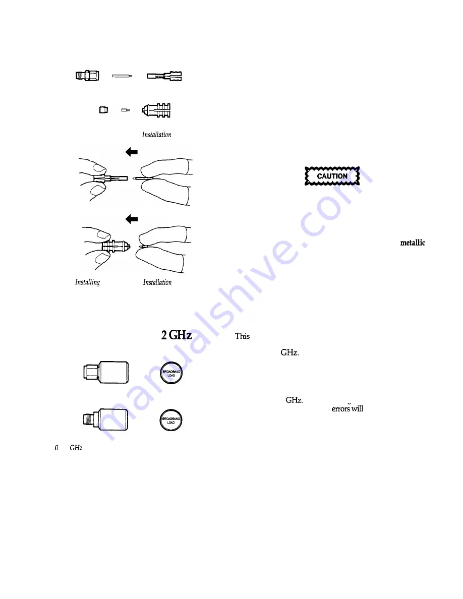
Air Lines Removed From
Tools
Each air line consists of a separate outer conductor and
center conductor and includes its own tool used for
installing and removing the parts from the test port. Both
are insertable. Each has a male end and a female end. The
male end of the air line fits into the installation tool.
The parts may be removed for inspection, if necessary, but
the tool is always used to install the parts for calibration.
Use extreme care in handling these parts. Use static dissi-
pative finger sheaths, or “finger cots” to prevent contami-
nation. Liquid or solid residue on the connector parts will
degrade performance. In particular, the inner conductors
can be easily deformed by squeezing. Do not use
tweezers or other devices to pick up or hold the parts.
the
Air
Lines in
Tools
0 to
Loads
implementation of the TRL 2-Port calibration allows
measurement of the loads to determine the error coeffi-
cients up to 2
Technically, the measurement is
treated as an infinite-length transmission line whose input
reflection is the reference impedance, Z,.
Note:
The male and female broadband loads are
manufactured to tolerances that assure equivalent responses,
at least below 2
If one is damaged or otherwise
becomes defective, calibration
result.
to 2
Loads -Male and Female Fixed Broadband Loads


