


Checklists
,QVWDOODWLRQFKHFNOLVW
37
o
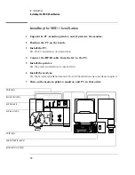
GC installation
o
Line voltage and outlet verified
o
GC unpacked and placed on an appropriate bench top
o
Carrier gas, trap, and GC plumbed with copper tubing
o
Plumbing purged with helium at 5 - 8 psi (35 - 55 KPa)
o
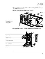
HP-IB and remote cables for MSD connected
o
Cables for ALS to the GC connected (optional)
o
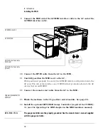
GC plugged in and turned on
o
Verify that the GC passes self test
o
HP-IB address in the GC set to 15
o
Column parameters configured
o
Carrier gas line pressure set to approximately 50 psi (345 KPa)
o
Carrier gas flow rate set to 7 ml per minute
o
Septum plugging end of column removed and end of column trimmed
o
Helium flow through column verified
o
Merlin Microseal installed (optional)
o
Injection port temperature set to 250°C
o
Oven temperature ramped from 40°C to 280°C at 15°C per minute and held
for 10 minutes.
o
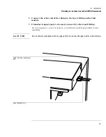
Upper front knockout in the GC exterior oven wall removed
o
The two large plastic knockouts removed from the GC left side panel.
o
ALS installed
o
Left side panel reinstalled, and GC/MSD interface cable routed through the
rear hole
o
GC power off (after temperature cycle complete)
Summary of Contents for 5973
Page 1: ...H Hardware Installation Manual HP 5973 Mass Selective Detector ...
Page 4: ...4 ...
Page 14: ...14 ...
Page 34: ...34 ...
Page 35: ...3 Checklists Installation checklist 36 Customer familiarization checklist 40 ...
Page 44: ...44 ...
Page 46: ...H Manual Part Number G1099 90006 Copyright 1998 Hewlett Packard Printed in USA 1 98 ...