


P/N 480-0005-00-15
3-5
Chapter 3: Installation
Connection
Introduction
The following steps are required to fully connect the Tenor CMS:
•
Connect to Trunk Interface - PSTN and/or to Line Side Interface - PBX
•
Connect to Ethernet LAN
•
Connect PC serial Com port
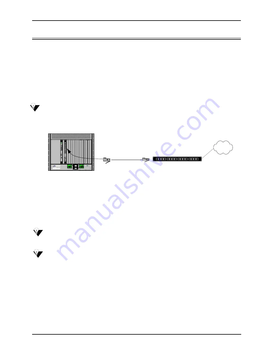
Connect to Trunk Interface - PSTN
NOTE:
For illustration purposes, the CMS (14 slot) DC unit with CPU card is shown.
Figure 3-2
Connect to Trunk Interface
1. Plug one end of the straight through RJ-48 cable into one of the eight WAN E1 or T1 ports on one of the
rear transition modules (for the associated T1, E1, or DS1 front cards). The cable from Quintum would be
the green RJ-48 cable. See
Chapter 2: Hardware Components
for cable pinouts if you are making your
own cables, or if you wish to attach the cable to a punch down block.
2. Connect the other end of the RJ-48 straight cable to the patch panel which houses your telephone lines.
NOTE:
If you are connecting to an external CSU, ensure the Digital Interface is configured as short haul (or
DSX-1), otherwise, configure the Digital Interface to DS-1 to enable the built-in CSU via Com-
mand Line Interface (CLI). See
Chapter 4: Getting Started with Command Line Interface (CLI)
.
NOTE:
Connecting to the patch panel may require trained telephone personnel.
10
1
2
3
4
DS1
1
2
3
4
10/100
Ethernet
Link TX/RX
Link TX/RX
1
2
3
4
Console
Config
1
2
3
4
10/100
Ethernet
Link TX/R X
1
2
3
4
CPU
Off
On
Off
On
0
1
Off
On
0
1
© Copyright 2001 Quintum Technologies Inc.
-48 |RTN|
-48 |RTN|
-48 |RTN|
-48 |RTN|
Chassis Rear
PSTN
Patch Panel
RJ-48


