background image

P/N 480-0005-00-15

1-12

Chapter 1: Overview

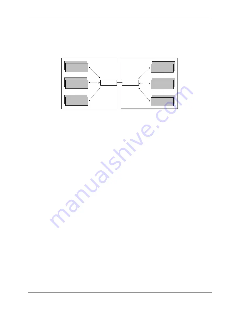
In addition, if you are using more than one CMS unit, you can configure one of the border elements for that 
zone. The Tenor CMS unit provides two border elements: primary and secondary. These work together as one 
entity to provide redundancy and fault tolerance; there are no hierarchical differences.

Call Services 

Gatekeepers provide services such as addressing, authorization and authentication of terminals and gateways, 
bandwidth management, accounting, billing, and charging. Gatekeepers also provide call-routing services. 
Specifically, the Tenor CMS Gatekeeper provides the functions which follow:

Address Translation. 

The gatekeeper translates telephone numbers into IP addresses and vice versa. It per-

forms Alias Address (phone number) to Transport Address (IP address) translation when an endpoint requests 
service. The Gatekeeper uses a translation table to translate an Alias Address (an address such as an H.323 
identifier that a user may not understand) to a transport address. The translation table is updated using Regis-
tration messages.

Autodiscovery.

 The gatekeeper is discovered in one of the following ways: An endpoint sends an IP broad-

cast called a Gatekeeper Request message (GRQ) message (which includes that correct gatekeeper name) to 
discover a Gatekeeper OR the endpoint will discover a gatekeeper by its IP address. 

Routing. 

The gatekeeper identifies the IP address of endpoints in its administrative domain. The gatekeeper 

builds a routing database from information obtained from the border element and also from gateways and 
H.323 endpoints. 

Admissions Control. 

All H.323 endpoints must register and request permission to enter the gatekeeper’s 

zone; the gatekeeper will confirm or deny access to the network.


The gatekeeper authorizes network access 

and protects the integrity of the network using Admissions Request (ARQ), Admissions Confirmation (ACF) 
and Admissions Reject (ARJ) messages. 

Configuration

For the Gatekeeper/Border Element functionality, the following items are configurable via Command Line 
Interface (CLI): 

Primary Border Element IP Address. 

The IP address for the administrative domain’s Border Element 

(the Border Element is internal to the Tenor CMS unit; it is used to establish relationships with other 

Border Element

Gatekeeper

Zone

Gatekeeper

Zone

Gatekeeper

Zone

Administrative Domain

Border Element

Gatekeeper

Zone

Gatekeeper

Zone

Gatekeeper

Zone

Administrative Domain

Summary of Contents for 480-0005-00-15

Page 1: ...N 480 0005 00 15 Tenor and Quintum are registered trademarks Tenor Carrier MultiPath Switch CMS PacketSaver Quintum Technologies Inc VoIP Made Easy TASQ SelectNet and SelectNet Technology are trade marks of Quintum Technologies Inc Switch CMS ...

Page 2: ...ing 1 4 Multiple Channels Signaling Supported 1 4 Fractional T1 E1 Support 1 4 PacketSaver 1 5 IVR RADIUS support 1 5 Easy Connect to Console 1 5 H 323 Gatekeeper Call Control Management 1 5 Powerful System Monitoring 1 6 Capabilities 1 7 Intra trunk Routing Hairpinning 1 8 Other Call Routing Options 1 9 Virtual Tie Line 1 9 Hop off PBX Call 1 10 SNMP Support 1 10 Call Detail Recording 1 10 H 323 ...

Page 3: ...w with AC power 2 12 Front view with DC power 2 13 Rear View with DC power 2 14 System Controller Card Available for CMS P1 5 x 2 15 CPU Card Available for CMS P2 x x 2 18 Front View 2 19 Rear View 2 20 WAN Cards 2 22 DS1 WAN Card with DSP module 2 22 T1 WAN Card 2 25 E1 WAN Card 2 27 DSP Resource Card 2 29 Cables 2 31 RJ 45 Cables 2 31 RJ 48 Cables 2 33 DB 9 to DB 9 Null Modem Cable for System Co...

Page 4: ...rial Requirements 3 11 Connect Power 3 11 Connect Power CMS960 8 slot and CMS240 2 slot DC only 3 14 Power Requirements 3 14 Material Requirements 3 14 Connect Power 3 14 Install Power Cord Strain Relief AC only 3 16 Power up the System for AC unit 3 17 Prevent Electrostatic Discharge Damage 3 18 ESD Antistatic Wrist Strap 3 18 Provide Grounding 3 18 Assign IP Address 3 19 Install Software Upgrade...

Page 5: ...ance mode 4 19 Monitor mode 4 20 Diagnostic Mode 4 21 Event Log 4 21 Configure Common CLI Options 4 22 Clock Source 4 22 Gatekeeper 4 22 Gateway 4 23 Border Element 4 23 Channel Group 4 23 Digital Interface 4 23 Switch Protocol 4 24 Trunk Group 4 24 Chapter 5 Working with SNMP What is SNMP 5 2 How does Tenor CMS utilize SNMP 5 2 Installation Requirements 5 3 Installation 5 4 Download and install S...

Page 6: ... 0 1 100 101 6 6 Sample Record for Extended CMS CDR Format 3 4 103 104 6 9 Chapter 7 System Alarms Monitor Alarms 7 2 How to Read Alarms 7 2 Valid Alarms 7 4 View Alarms 7 8 Display all Alarms 7 8 Display Active Alarms 7 8 Display Alarm History 7 9 Chapter 8 Diagnostics Maintenance Before you Begin 8 2 Diagnostics 8 3 Common Symptoms Problems 8 3 Unit Provisioning 8 4 Ping Unit 8 4 Inspect and Rep...

Page 7: ...ace WAN System Controller CPU cards of identical type 8 14 Replace Change DSP Module on DS1 card 8 16 Move card location or change card type 8 19 If you need Additional Help 8 20 Appendix A Getting Acquainted with Tenor CMS in the VoIP Network Appendix B Specifications Approvals GLOSSARY INDEX WARRANTY ...

Page 8: ...P N 480 0005 00 15 1 About this Guide ...

Page 9: ...how to access the CLI and execute commands A description of each CLI mode is also included Chapter 5 Working with SNMP This chapter describes the SNMP protocol and how to use it with the Tenor CMS Chapter 6 Call Detail Recording Describes the Call Detail Recording CDR feature including how to set up the CDR server and assign a password In addition instructions for reading CDR output is also includ...

Page 10: ...special text that are designed to reveal supplemental information Note Warn ing and Caution See below A NOTE provides additional helpful information This information may tell you how to do a certain task or just be a reminder for how to s given in previous sections i e For a list of valid commands at any time type A WARNING provides information about how to avoid harm to your VoIP equipment or oth...

Page 11: ...ossary defines specific terms See Appendix A Getting Acquainted with Tenor CMS in the VoIP Net work for detailed information about VoIP terms and concepts Extensive configuration help is available via the Command Line Interface help system Just type help or from any prompt to obtain help See Chapter 4 Getting Started with Command Line Interface CLI for more information ...

Page 12: ...f the Tenor Carrier MultiPath Switch CMS including feature descriptions and capabilities You will also find information about the organization of this product guide Specifically the following topics are covered A description of Tenor CMS Typical implementations Features and capabilities ...

Page 13: ...activity in the unit The DS1 T1 and E1 cards provide connections The DS1 card also provides DSP processing DSP is a signal processing resource it performs CMS 14 Slot CMS960 8 Slot A C Power Supply Power QUINTUM TECH NOLOGIES IN C TM TECHNOLOGIES INC QUINTUM TM Hot Swap DS1 Span Status 4 8 3 7 2 6 1 5 10 100 Ethernet DSP Link Alarm CPU 1 1 2 2 Bank TX RX Status PCI TECHNOL OGIES INC QUINTUM TM CPU...

Page 14: ...C or DC power A high performance backplane supports two types of chassis side busses TDM and packet TDM supports 2048 full duplex channels it is used for transporting circuit switched traffic The packet bus is used for carry ing packet oriented data The slotted system architecture enables you to set the VoIP capabilities to suit your network s needs it is available in three configurations CMS 14 s...

Page 15: ...fy the call origination site trunk circuit line circuit or IP routing group and then route the call according to any parameters you configure in the routing database Each call may be routed via circuit switched path between any two circuit groups or compressed and transported via VoIP when con necting to an IP routing group Trunk circuits are those that typically connect to another circuit switche...

Page 16: ...between the network access gateway and the billing server As a result the RADIUS enables the Tenor CMS to interoperate directly with billing server application software from a wide range of vendors To provide redundancy the Tenor supports two RADIUS servers Pri mary and Secondary Easy Connect to Console Plugging a serial cable for CPU or null modem cable for System Controller between the System Co...

Page 17: ...he front of WAN interface cards as well as on the DSP cards and the System Controller CPU card The LEDs light up according to operations and alarms the system is experi encing Through the Command Line Interface CLI management system you can view a list of active system alarms as well as view an alarm history Each alarm indicates the chassis s operational status Tenor CMS is also SNMP capable with ...

Page 18: ...ecision made by the Tenor CMS is based upon your configuration and the dialed number Figure 1 2 Line Circuit Call Routing Line Circuits Ethernet PSTN B Trunk Circuits Trunk Circuits PSTN A Ethernet IP Network Tenor CMS PBX VOIP Call Circuit Call Circuit Call 0 1 Reset 3 3V 5V 12V 12V QUINTUM TECHNOLOGIES INC TM QUINTUM TECHNOLOGIES INC TM TM Fault Fault TM Ground Strap Status Alarm C PU PCI Reset ...

Page 19: ...Ethernet IP Network Tenor CMS PBX VOIP Call Circuit Call Circuit Call 0 1 Reset 3 3V 5V 12V 12V QUINTUM TECHNOLOGIES INC TM QUINTUM TECHNOLOGIES INC TM TM Fault Fault TM Ground Strap Status Alarm C PU PCI Reset 10 100 Ethernet Link TX RX 1 2 3 4 QUINTUM TM TECHNOLOGIES INC Hot Swap CPU Hot Swap DS1 Status Alarm 1 2 PCI CPU B ank DSP 1 2 TX RX Link 1 2 3 4 5 6 7 8 10 100 Ethernet Span Status TECHNO...

Page 20: ...rs are phone numbers that are reachable through local Line Circuits Hop Off Directory Numbers are phone numbers that can be routed over the IP to another Tenor location and then out to the Trunk circuit possibly to the PSTN as a local call Static Routes are used between networks and other H 323 devices that are not registered to the network through the Border Element such as non Quintum gateways V...

Page 21: ...Management Protocol SNMP the standard protocol used to exchange network information between different types of networks The Tenor CMS unit acts as an SNMP agent using HP Openview to receive commands and issue responses to the network manager The network manager will then be able to perform certain functions such as receiving traps from Tenor CMS Call Detail Recording Through the Call Detail Record...

Page 22: ...es call routing services for its zones through gatekeeper to gatekeeper messages or gatekeeper to border element messages see Border Element for more information Call Registration H 323 endpoints in the same zone register with the designated gatekeeper When registration is complete and a call is originated the call request is sent to the gatekeeper The call request provides the Gatekeeper with the...

Page 23: ...overed in one of the following ways An endpoint sends an IP broad cast called a Gatekeeper Request message GRQ message which includes that correct gatekeeper name to discover a Gatekeeper OR the endpoint will discover a gatekeeper by its IP address Routing The gatekeeper identifies the IP address of endpoints in its administrative domain The gatekeeper builds a routing database from information ob...

Page 24: ...t the IP address the Tenor CMS uses as a Border Element is in the administrative zone There is generally only one sec ondary Border Element in each organization Discovery IP Address The IP address a Tenor CMS uses to communicate with a Gatekeeper for service Discovery Port The H 323 standard port a Tenor CMS uses to discover a Gatekeeper Registration Port The H 323 standard port a Tenor CMS uses t...

Page 25: ...pter 2 Hardware Components This chapter tells you what is contained in your hardware package A description of each component is also included Specifically the following topics are covered Chassis Power Supplies WAN Cards Cables ...

Page 26: ...ection as well as power cord connection For the DC unit the front side of the chassis provides access to WAN cards T1 E1 DS1 DSP cards the sys tem controller CPU card and power supplies The rear side exposes the back portion of the transition cards for network connections as well as the circuit breakers power receptacles and power plugs Through all of these units you can connect up to four differe...

Page 27: ...ing feature enables one power sup ply to take over if the other fails System Fans Two system fans accessible through a swing down panel via thumb screws are used to cool the chassis These fans are hot swappable meaning you can remove replace the fans while the unit is operational Reset Button Enables you to reset the system This function will be supported in a future release Ground Strap Socket A ...

Page 28: ... 2 DS1 cards and the CPU Card Figure 2 2 Tenor CMS Rear View AC unit WAN Card Slots The rear of the T1 E1 or DS1 WAN cards the transition modules is used for net work connection The quantity will vary depending upon the number of WAN cards you have inserted Power Inlet Inlet for which you insert the supplied AC power cord The unit requires a 110 240 VAC Earth Ground Stud A Ground Stud is provided ...

Page 29: ...p Socket A ground connection is provided for ESD protection Air Filter The Air Filter is accessible by opening the lower front panel You do not have to turn off the chassis For cleaning see Chapter 8 Diagnostics Maintenance Chassis LEDs The LEDs are indicators as to the status of the four voltage supplies When these are lit they indicate the respective voltages are being output from the power supp...

Page 30: ... receptacle connection The top circuit breaker controls the left power receptacle the bottom circuit breaker controls the right power receptacle When you push the rocker to ON the breaker will be closed a red indicator shows the user that the contacts are closed When you push the rocker to OFF the contacts will open Both circuit breakers must always be open even if only one power source is connect...

Page 31: ... ensures redundancy if any one of the three fail Wrist Strap Ground Socket Socket available in which to connect an ESD wrist strap for ESD protec tion Power Supplies Card Slots A C Power Supply Power QUINTUM TECH N OLOGIES IN C TM QUINTUM TECH N OLOGIES IN C TM TECHNOL OGIES INC QUINTUM TM Hot Swap DS1 Span Status 4 8 3 7 2 6 1 5 10 100 Ethernet DSP Link Alarm CPU 1 1 2 2 Bank TX RX Status PCI A C...

Page 32: ...tal power down of the Tenor CMS i e if the power cord is accidentally pulled the strain relief will relieve pressure put on the cord Fuse Replaceable fuse See Chapter 8 Diagnostics Maintenance for more information Supplementary Earth Ground A supplementary earth ground connection is provided Wrist Strap Ground Socket Socket available in which to connect an ESD wrist strap for ESD protec tion Power...

Page 33: ... Power Alarm QUINTUM TECH N OLOGIES IN C TM QUINTUM TECH N OLOGIES IN C TM TECHNOL OGIES INC QUINTUM TM Hot Swap DS1 Span Status 4 8 3 7 2 6 1 5 10 100 Ethernet DSP Link Alarm CPU 1 1 2 2 Bank TX RX Status PCI D C Power Supply Power Alarm QUINTUM TECH N OLOGIES IN C TM TECHNOL OGIES INC QUINTUM TM CPU 4 8 3 7 2 6 1 5 Alarm CPU 2 Status PCI Reset 10 100 Ethernet Link TX RX Hot Swap D C Power Supply...

Page 34: ...40 to 60 VDC power Supplementary Earth Ground A supplementary earth ground connection is provided Circuit Breaker There is one circuit breaker for each power connection lettering on each one indicates which breaker controls which power receptacle connection When you push the rocker to ON the breaker will be closed a red indicator shows the user that the contacts are closed When you push the rocker...

Page 35: ...power Figure 2 9 Tenor CMS240 Front View DC unit Card Slots Two slots are available for WAN cards T1 E1 DS1 DSP cards and the CPU System Con troller card Power Supply One AC Power Supply Wrist Strap Ground Socket Socket available in which to connect an ESD wrist strap for ESD protec tion A C Power Supply Power QUINTUM TECHNOLOGIES INC TM TECHNOL OGIES INC QUINTUM TM Hot Swap DS1 Span Status 4 8 3 ...

Page 36: ... A switch to turn power on and off Fuse Replaceable fuse See Chapter 8 Diagnostics Maintenance for more information Supplementary Earth Ground A supplementary earth ground connection is provided Card Slots The rear of the cards requiring a transition module T1 E1 DS1 CPU is used for network connection The quantity will vary depending upon the number of cards you have inserted Wrist Strap Ground So...

Page 37: ...ly Wrist Strap Ground Socket Socket available in which to connect an ESD wrist strap for ESD protec tion D C Power Supply Power Alarm QUINTUM TECHNOLOGIES INC TM TECHNOL OGIES INC QUINTUM TM Hot Swap DS1 Span Status 4 8 3 7 2 6 1 5 10 100 Ethernet DSP Link Alarm CPU 1 1 2 2 Bank TX RX Status PCI TECHNOLOGIES INC QUINTUM TM CPU 4 8 3 7 2 6 1 5 Alarm CPU 2 Status PCI Reset 10 100 Ethernet Link TX RX...

Page 38: ...ct the power cord strain relief to the unit A power cord strain relief is a plastic device designed to avoid accidental power down of the Tenor CMS i e if the power cord is accidentally pulled the strain relief will relieve pressure put on the cord Power Terminal Provides screw terminal wire connections to the 40 to 60 VDC power Supplementary Earth Ground A supplementary earth ground connection is...

Page 39: ...k cards via PCI bus As the central point of system resource management the system controller card implements the intelligent call routing and IP call signaling The card also acts as an interface through which the user is able to perform net work and system management functions The system controller card is always inserted in slot 14 for the CMS the slot nearest the power supplies identified with a...

Page 40: ...able 2 2 Input Output Signals for 10 100 Ethernet Port Pin Signal Definition Color 1 TX Transmit Data White w orange 2 TX Transmit Data Orange 3 RX Receive Data White w green 4 RSVD Reserved Blue 5 RSVD Reserved White w blue 6 RX Receive Data Green 7 RSVD Reserved White w Brown 8 RSVD Reserved Brown ...

Page 41: ...h used for internal Quintum use only LEDs LEDs provide a high level indication of the system controller card activity Basic definitions follow See Chapter 8 Diagnostics Maintenance for a detailed description for troubleshooting purposes BFL Steady yellow light indicates the board has failed CPU Green light indicates the CPU bus is active PCI Green light indicates that the local PCI bus is busy CPC...

Page 42: ...e through which the user is able to perform network and sys tem management functions When CPU card is inserted in the slot it connects to an associated Rear Transition Module RTM in the rear of chassis NOTE For the purposes of this document the term CPU card indicates the CPU application card and transition module as a single unit Through the CPU card you are able to perform system functions such ...

Page 43: ...n light indicates the CPU bus is active PCI Green light indicates that the local PCI bus is busy Port For future use Reset Resets the CPU card along with the entire chassis Ethernet LEDs The CPU card contains four Link and TX RX Status LEDs viewable from the front of the chassis to provide a high level indication of the system operational mode and chassis activity including alarm activity Each Lin...

Page 44: ...tivity 10 100 Base T Ethernet port The Ethernet port one port is functional the other three ports are not used provides an RJ 45 jack for an individual connection to a 10 100 Ethernet LAN switch or hub via RJ 45 cable The Ethernet port is individually configured with a unique IP and MAC address Figure 2 18 10 100 BASE T Ethernet Port Pin Order Link LEDs 10 100 Ethernet ports Console Port Config Sw...

Page 45: ...Table 2 5 Serial RS232 DB 9 Connector Pinouts Config switch For internal Quintum use only Pin Signal Definition Color 1 TX Transmit Data White w orange 2 TX Transmit Data Orange 3 RX Receive Data White w green 4 RSVD Reserved Blue 5 RSVD Reserved White w blue 6 RX Receive Data Green 7 RSVD Reserved White w Brown 8 RSVD Reserved Brown Pin Function Description 1 RSVD Reserved 2 RXD Receive Data 3 TX...

Page 46: ...ital Signal Processor an interchangeable part of the DS1 card is a signal processing module The DSP provides the required signal processing functions to implement VoIP The DSP module compresses voice data and generates voice packets using PacketSaver Quintum s exclusive multiplexing technology Each DS1 supports up to two DSP modules each module supports up to 120 voice channels Although appli cati...

Page 47: ...ion of the DSP card activity See Chapter 8 Diagnostics Main tenance for a detailed description for troubleshooting purposes DSP Bank 1 Lights for DSP module activity on the first DSP module DSP Bank 2 Lights for DSP module activity on the second DSP module For both DSP banks red indicates power up or DSP module is usable green indicates at least one DSP chan nel is in use Unlit indicates the DSP i...

Page 48: ...ber Remote alarm generated i e remote side has a problem and is sending a Yellow alarm Hot Swap LED A lit blue light indicates that the DS1 card is not in service RJ 48 Input Output ports The eight RJ 48 connectors on the rear of the DS1 card the transition module are used to provide network access they route signals between the T1 or E1 and a piece of network equipment i e PBX or PSTN The input o...

Page 49: ... slots when facing the front of the chassis A crossover cable is required when connecting to a Line side PBX interface when supplied by Quintum this is a red RJ 45 cable A straight cable is required when connecting to the Trunk side PSTN interface when supplied by Quintum this is a green RJ 45 cable Figure 2 22 T1 WAN Card Span LEDs The T1 card contains eight Span Status LEDs viewable from the fro...

Page 50: ...48 connectors on the rear of the T1 card the transition module are used to provide network access they route signals between the T1 and a piece of network equipment i e PBX or PSTN The input output signals are listed in Table 2 7 Figure 2 23 RJ 48 Port Pin Order Table 2 7 Input Output Signals for WAN T1 Card RJ 48 Ports Port Pin Signal Definition 1 8 1 RR Receive Ring 1 8 2 RT Receive Tip 1 8 3 N ...

Page 51: ...n Channel Signaling CCS For the CMS 14 slot you can insert the E1 card in slots 1 through 4 when facing the front of the chassis A crossover cable is required when connecting to a Line side PBX interface when supplied by Quintum this is a red RJ 45 cable A straight cable is required when connecting to the Trunk side PSTN interface when supplied by Quintum this is a green RJ 45 cable Figure 2 24 E1...

Page 52: ...only RJ 48 Input Output Ports The eight RJ 48 ports on the rear of the E1 card transition module are used to provide network access they route signals between the E1 and a piece of network equipment i e PBX or PSTN The input output signals are listed in Table 2 8 Figure 2 25 RJ 48 Port Pin Order Table 2 8 Input Output Signals for WAN E1 Card RJ 48 Ports Port Pin Signal Definition 1 8 1 RR Receive ...

Page 53: ...6 Figure 2 26 DSP Card Channel support Each DSP board supports 120 voice channels A maximum of eight cards can be installed in a system Although application specific the number of calls going VoIP determines how many DSP cards will be required In general two DSP cards are required for each fully utilized WAN T1 or WAN E1 card See Table 2 9 for the required number of DSP cards per various T1 or E1 ...

Page 54: ...ard activity on that bank DSP Bank 1a Lights when DSP card activity is more than 50 DSP Bank 2 Lights for any DSP card activity on that bank DSP Bank 2a Lights when DSP card activity is more than 50 DSP Bank 3 Lights for any DSP card activity on that bank DSP Bank 3a Lights when DSP card activity is more than 50 DSP Bank 4 Lights for any DSP card activity on that bank DSP Bank 4a Lights when DSP c...

Page 55: ... in Figure 2 27 Figure 2 27 RJ 45 Pin Order Cable Usage RJ 48 to RJ 48 Crossover Cable this cable is red if provided by Quintum All units T1 E1 connection to Line Side PBX inter face RJ 48 to RJ 48 Straight Through cable this cable is green if provided by Quintum All units T1 E1 connection to Trunk Side PSTN inter face T1 E1 connection to external CSU RJ 45 Ethernet cable grey All units Connection...

Page 56: ...ns are applicable to the RJ 45 cable provided Figure 2 28 RJ 45 10 100BT Connector Pinouts Table 2 11 RJ 45 10 100BT Connector Pinouts Pin Signal Definition Color 1 TX Transmit Data White w orange 2 TX Transmit Data Orange 3 RX Receive Data White w green 4 Unused Unused Blue 5 Unused Unused White w blue 6 RX Receive Data Green 7 Unused Unused White w Brown 8 Unused Unused Brown Pin Connects to Pin...

Page 57: ...1 E1 straight cable is used to connect Tenor CMS T1 E1 or DS1 WAN cards to the Trunk Side PSTN Cable pinouts are provided below If this cable is provided by Quintum the color is green The color specifications are applicable to the RJ 48 straight cable provided Figure 2 30 RJ 48 T1 E1 DS1 Connector Pinouts Table 2 12 RJ 48 Connector Pinouts for T1 E1 DS Pin Signal Definition Color 1 RX ring Receive...

Page 58: ...ions are applicable to the RJ 48 crossover cable provided Figure 2 31 RJ 48 Crossover Cable Pinouts Table 2 13 RJ 48 Connector Pinouts for T1 E1 DS1 Pin Signal Definition Color for Connector 1 Color for Connector 2 1 RX ring Receive Ring White w orange Blue 2 RX tip Receive Tip Orange White w blue 3 RSVD Reserved 4 TX ring Transmit Ring Blue White w orange 5 TX tip Transmit Tip White w blue Orange...

Page 59: ...nectors are shown in Figure 2 32 and Figure 2 33 Figure 2 32 DB 9 Male Connector Pin Order Figure 2 33 DB 9 Female Connector Pin Order Figure 2 34 DB 9 Connector Pinouts Table 2 14 DB 9 Connector Pinouts Pin Function Description Pin 1 RSVD Reserved 1 2 RXD Receive Data 2 3 TXD Transmit Data 3 4 RSVD Reserved 4 5 GND Signal Ground 5 6 RSVD Reserved 6 7 RSVD Reserved 7 8 RSVD Reserved 8 9 N C Not Co...

Page 60: ...s are shown in Figure 2 35 and Figure 2 36 Figure 2 35 DB 9 Male Connector Pin Order Figure 2 36 DB 9 Female Connector Pin Order Figure 2 37 DB 9 Connector Pinouts Table 2 15 DB 9 Connector Pinouts Pin Function Description Pin 1 RSVD Reserved 1 2 RXD Receive Data 2 3 TXD Transmit Data 3 4 RSVD Reserved 4 5 GND Signal Ground 5 6 RSVD Reserved 6 7 RSVD Reserved 7 8 RSVD Reserved 8 9 RSVD Reserved 9 ...

Page 61: ...of the chassis If one of the power supplies is removed or becomes inoperable the system will derive its power from the remaining power supply Figure 2 38 Power Supplies Power Status LED There is one LED on each power supply to indicate whether it is functioning correctly There are two colors for the LED red or green Green indicates AC input red indicates that input output failed or there is a powe...

Page 62: ...ectly If this LED is lit the Alarm LED will be unlit Alarm LED Red LED indicates that input output failed or there is a power fault If this LED is lit the Power LED will be unlit NOTE For illustration purposes the CMS960 8 slot with AC is shown Figure 2 39 CMS960 AC Power Supplies A C Power Supply Power QUINTUM TEC H NOLOGIES IN C TM QUINTUM TEC H NOLOGIES IN C TM TECHNOL OGIES INC QUINTUM TM Hot ...

Page 63: ...ult With DC Power There are two LEDs Power and Alarm See below Power LED Green LED indicates whether the power supply is functioning correctly If this LED is lit the Alarm LED will be unlit Alarm LED Red LED indicates that input output failed or there is a power fault If this LED is lit the Power LED will be unlit NOTE For illustration purposes the CM240 2 slot with AC is shown Figure 2 40 CMS240 ...

Page 64: ...stallation instructions as well as how to position the chassis successfully within your network Specifically the following topics are covered Pre Installation guidelines Position the chassis Connect to Line Circuit Trunk Circuit LAN and PC Upgrade backup restore procedure ...

Page 65: ...ware ensure the following components are included in your shipment Tenor CMS chassis and Mounting Hardware 1 AC Power Cable for AC units only DB 9 Serial Null Modem Cable for System Controller card yellow cable if provided by Quintum DB 9 RS 232 Serial Cable for CPU card grey if provided by Quintum RJ 45 LAN Cable 1 ESD Wrist Strap Cards and WAN cables associated with your custom configuration Pow...

Page 66: ...ll the chassis in a rack as follows 1 Choose a position for the chassis within the rack WARNING If the Tenor CMS chassis is the only equipment installed in the rack ensure it is level with the rack to avoid the rack from becoming unbalanced Mount as low as possible to avoid a high center of gravity NOTE For illustration purposes the CMS 14 slot is shown installed in the rack 2 Align the chassis mo...

Page 67: ...12V QUINTUM TECHNOLOGIES INC TM QUINTUM TECHNOLOGIES INC TM TM Fault Fault TM Ground Strap Status Alarm CPU PCI Reset 10 100 Ethernet Link TX RX 1 2 3 4 QUINTUM TM TECHNOLOGIES INC Hot Swap CPU Hot Swap DS1 Status Alarm 1 2 PCI CPU Bank DSP 1 2 TX RX Link 1 2 3 4 5 6 7 8 10 100 Ethernet Span Status TE CHNOLOGIE S INC QUINTUM TM ...

Page 68: ...re Components for cable pinouts if you are making your own cables or if you wish to attach the cable to a punch down block 2 Connect the other end of the RJ 48 straight cable to the patch panel which houses your telephone lines NOTE If you are connecting to an external CSU ensure the Digital Interface is configured as short haul or DSX 1 otherwise configure the Digital Interface to DS 1 to enable ...

Page 69: ...apter 2 Hard ware Components for cable pinouts if you are making your own cables 2 Connect the other end of the crossover RJ 48 cable into the appropriate port on the PBX If another cable or adapter is required see Chapter 2 Hardware Components for RJ 48 crossover pinout information NOTE If you are connecting to an external CSU ensure the Digital Interface is configured as short haul or DSX 1 othe...

Page 70: ...ion purposes the unit is shown with a CMS 14 slot with AC power Figure 3 4 Connect to Ethernet Hub Switch 1 Plug one end of the grey RJ 45 ethernet cable into the front of the System Controller card s port labeled 10 100 Ethernet 2 Plug the other end of the cable into your Ethernet hub switch If a custom cable or adapter is required see Chapter 2 Hardware Components for the Ethernet RJ 45 10 100 p...

Page 71: ...ower Figure 3 5 Connect to Ethernet Hub Switch 1 Plug one end of the grey RJ 45 ethernet cable into one of the ports on the CPU rear transition module labeled 10 100 Ethernet 2 Plug the other end of the cable into the Ethernet hub switch port If a custom cable or adapter is required see Chapter 2 Hardware Components for Ethernet RJ 45 10 100 Data Network Ethernet Hub Switch Chassis Rear AC view 10...

Page 72: ...er card s port labeled Console See Chapter 2 Hardware Components for RS 232 connector pinouts 2 Insert the female end of the DB 9 cable into your workstation s serial port see your PC documentation for more information about this port DB 9 Multi Path Voice Gateway TM TECHNOLOGIES INC QUINTUM Another Fine Product From 0 1 Reset 3 3V 5V 12V 12V QUINTUM TECHNOLOGIES INC Console ABT BFL CPU CPCI PCI 2...

Page 73: ...or see section Chapter 2 Hardware Components for pinouts to connect the chassis to a PC 1 Insert the male end of the DB 9 cable grey cable if provided by Quintum into the CPU card s rear port labeled Console See Chapter 2 Hardware Components for serial RS 232 connector pinouts 2 Insert the female end of the DB 9 cable into your workstation s serial port see your PC documentation for more informati...

Page 74: ...ntry specific electrical installation codes Figure 3 8 DC Power Panel located on bottom rear of chassis The top circuit breaker controls the left power inlet and the bottom circuit breaker controls the right power inlet See Figure 3 8 Each circuit breaker has a dual colored rocker Pushing down on the left side of the breaker ON 1 will close the switch and expose a red indicator that shows the user...

Page 75: ...on sequence 6 Once the connections are complete between the DC feed s and the Tenor CMS power plug s insert the plugs into the power receptacles 7 Secure the power plugs to each of the power receptacles by torquing the screws in the face of the plug to between a minimum of 4 4 lbs in 0 5Nm and a maximum of 5 3 lbs in 0 6Nm with the same screw driver See Figure 3 12 Plug and secure both power plugs...

Page 76: ...very 12 inches from the strain relief to the DC source so as not to disturb the field wiring 9 Close the on site over current protection device to supply power to the inlet s of the Tenor CMS The chassis power connections are now complete With the WAN cards and power supplies secured to the chassis close the circuit breaker s on the Tenor CMS Verify that the STATUS LEDs on the power supplies are g...

Page 77: ...mum of 10 AWG min 2 0 mm2 max 5 0 mm2 and insulation rated at a minimum of 90 C or better must be used for all wires to the power inlets Connect Power WARNING Before making any changes to the wiring of your Tenor CMS turn off both circuit breakers and open the upstream disconnect switches at the source of the DC power feeds NOTE The electrical installation must comply with the National Electrical ...

Page 78: ...See Figure 3 9 Figure 3 14 Strip away wire 3 Insert the wire into the connector in the position shown in Figure 3 10 Figure 3 15 Connector position 4 Secure by tightening the clamping screw with a straight blade screwdriver of size 0 023x 0 137 0 6 x 3 5mm Screws must be torqued between a minimum of 4 4 lbs in 0 5 Nm and a maximum of 5 3 lbs in 0 6 Nm WARNING Do not over torque the screws 5 Repeat...

Page 79: ...ieve pressure put on the cord Install the strain relief as follows 1 Loop the strain relief s long plastic piece around the power cord and insert the end of the plastic rivet through the hole at the opposite end to create a clamp See Figure 3 16 Figure 3 16 Loop the strain relief around the power cord 2 Push the rivet into the Strain Relief Mount at the rear of the unit See Figure 3 17 Figure 3 17...

Page 80: ... using the supplementary Earth Ground post see Prevent Electrostatic Dis charge Damage 4 Locate the on off switch on the front of the chassis For Tenor CMS 14 slot or the rear of the chassis for CMS 240 and CMS960 click the switch to On The chassis will power up and the LEDs will flash and turn off For information about the LEDs see Chapter 8 Diagnostics Maintenance Once the chassis is powered up ...

Page 81: ... on your wrist when handling any of the components Use the following precautions when using the ESD strap When handling peripheral boards touch only the edges Do not touch any other components on the board including the connector pins Place the peripheral board in a static shielding bag or on an antistatic surface Avoid any component touching your clothing The Ground Strap protects components from...

Page 82: ...n i e name for each chassis such as Routing Server 4 Click Ok 5 Choose the connection port on your PC from the Connect Using drop down list box i e Direct to Com 1 Click Ok The Com1 Properties window will be displayed See Figure 3 18 Figure 3 18 Port Settings Window 6 From the Bits Per Second drop down list box choose 38400 7 From the Data Bits drop down list box choose 8 8 From the Parity drop do...

Page 83: ...port NOTE If you are unsure of the following values contact your network administrator 16 For IP address enter the IP address for the Tenor CMS chassis 17 For Subnet Mask for LAN prompt enter the subnet mask This address is used to differentiate the network portion of the IP address from the host portion of the IP address 18 For Default Gateway choose whether there should be a default gateway rout...

Page 84: ...re you have the CD that was shipped with your unit This CD contains upgrade files you are installing Upgrade from Disk 1 Access the CD ROM you received from Quintum and access CDROM Drive Software Upgrade Util ity The latest copy of the upgrade utility is also available from www quintum com 2 Double click on CMS Upgrade Wizard The Quintum Tenor CMS System Update Utility main screen will be display...

Page 85: ...ected system software Click Yes to continue the upgrade 9 A window will appear asking you to select the directory in which the new upgrade will be installed from 10 Select the appropriate upgrade file i e c Tenor_CMS CMSupgrade2 2 1 file and click Ok The Quin tum Tenor CMS Upgrade Utility window will be displayed 11 Enter the Tenor CMS IP Address for the IP address of the unit you want to upgrade ...

Page 86: ...up Follow the backup procedures from steps 4 8 from the Upgrade from Disk instruc tions When backup is complete the Quintum Logon Authentication window will be displayed See Figure 3 21 Figure 3 21 Quintum Login Authentication 3 Enter User ID and password The user name and password are used for new software downloaded from the quintum ftp server Typical entries are r1344 user name and qrf4735z91 1...

Page 87: ...ess the Quintum Tenor CMS Upgrade Utility main window 2 Click on Restore A window will appear asking you to select the directory where the file is located that you would like to restore 3 Select the desired file The Quintum Tenor CMS Restore window will be displayed 4 Enter the Tenor CMS IP Address for the IP address of the unit where the file is to be restored 5 Enter your User ID 6 Enter the pas...

Page 88: ...g Started with Command Line Interface CLI This chapter tells you to how use access the CLI and understand the CLI modes Specifically the following topics are included Access CLI Understand CLI modes View Menu Tree Use Mode specific commands ...

Page 89: ... result you can issue a command for Slot 3 to navigate to the option that represents Slot 3 Based on te chassis the system can have 2 8 or 14 slots Physical options such as Slot are assigned by the system and cannot be added or removed there are always 14 slots in a system Other options are part of the default system such as dial plan You can configure the dial plan and the corresponding attribute...

Page 90: ...status Navigation There are several options for navigating through the system You can either type in the desired option at the prompt or use global commands such as the surf or plus Enter key to move back and forth between the menu See Execute commands later in this chapter for specific information about each command User Login IDs There are two types of user logins user and admin The admin level ...

Page 91: ...ustrates the basic configu ration options See CLI Menu Tree Expanded View for a complete list of all CLI options CLI Menu Tree Basic View Figure 4 1 Menu Tree Basic View SIte VoIP DialPlan IPDialPlan PRIVateNumberingPlan PUBlicNumberingPlan MasterChassis DoMain BorderElement ZoNe Slots 1 14 DeVice DigitalInterface EthernetInterface GateWay AutoSwitchNumber BypassNumberDirectory HuntLDNDirectory pu...

Page 92: ... continued SYSLogServer 1 SYSLogPort SYSLogIPAddr SYSLogFacility SYSLogServer 2 SYSLogPort SYSLogIPAddr SYSLogFacility SYSLogServer 3 SYSLogPort SYSLogIPAddr SYSLogFacility CDRServer 1 CDRFormat CDRServerPort CDRServerIPAddr CDRPassWord CDRServer 2 CDRFormat CDRServerPort CDRServerIPAddr CDRPassWord CDRServer 3 CDRFormat CDRServerPort CDRServerIPAddr CDRPassWord CDRServer 4 CDRFormat CDRServerPort...

Page 93: ...ssPort ServiceAddressIPAddr ZOne GateWay NumberDirectories BypassNumberDirectory 1 HuntLDNDirectory pub1 HuntLDNDirectory prv1 HopoffNumberDirectory 1 AutoSwitchNumberDir 1 VoIPNetwork DoMain ZoNe GateWay VoiceCodec CodecVoiceCoding CodecPayloadSize CodecProfile 1 VoiceCodecAttached 1 VoiceCodecAttached 2 VoiceCodecAttached 3 8 CASSignalingGroup The following applies to E M only name ORrientation ...

Page 94: ...ughID MaxHopoffCallsAllowed TwoStageDialing AccessNumber AccessFormat ProvideAutoSwitchProgressTone VoIPNetwork DoMain ZoNe GateWay TrunkCircuitRoutingGroup cont IVRType Hairpinning IVRRequestPreferredLanguage EnableExternalRouting MaxTalkTime AutoSwitchNumberAttached HopoffNumberDirAttached 1 HopoffNumberDirAttached 2 32 LineCircuitRoutingGroup name OverlapDial DIRection ProgressTone PubOrPrivNum...

Page 95: ...itRelay PacketSaverEnabled MaxIncomingCallsAllowed EnableExternalRouting MaxOutgoingCallsAllowed MaxTalkTime CodecProfileAttached IPDialPlanAttached ToneProfile name DiscToneFreq1 DiscToneFreq2 DiscToneONTime DiscToneOFFTime GateKeeperParam DiscoveryAddressIPAddr MulticastDiscoveryIPAddr PrimaryBEIPAddr SecondaryBEIPAddr ZoneName PassWord EndPointAddressDirectory QOSPolicy AutoSwitchThreshold Rout...

Page 96: ...og box will be displayed Type telnet and click on Ok Or type telnet followed by the IP address and you will connect 2 At the telnet prompt type open followed by the IP address for the unit to which you want to connect A connection to the Tenor CMS unit will be established Serial Port Connection When the Tenor CMS is first shipped to you you must connect to the unit using this method to assign an I...

Page 97: ... down list box choose None 13 Click on Call Call A connection to the CMS unit will be established 14 Enter a login name The default login name is admin 15 Enter a password The default password is admin To change this password later see Chapter 8 Diagnos tics Maintenance Questions about the unit will scroll on the screen NOTE Steps 16 18 are used for first time assignment of IP address 16 For IP ad...

Page 98: ... To move from one menu tree to another type the name of the menu item to which you want to go Move between modes To move from one mode to another type the desired command at any time Use the following table as refer ence Move within modes To move to any other CLI menu item type the desired menu item from the current prompt To reach Enter Configuration config or co Diagnostic diagnostic or diag Mai...

Page 99: ... Global commands apply to any object or action within the CLI they are basic commands that can be executed from any point in the CLI Each global command is detailed below Goto Select and jump to any option for configuration maintenance monitoring or diagnostic To select and jump to any location you do not need to type go to just type any other prompt name Example slot 12 The prompt for slot 12 wil...

Page 100: ...d exits you to the previous option in the menu tree the exit command enables you to exit out of all menu items To use these commands type exit or exit at the prompt For the exit command the last option you exit into is the company prompt i e if the company prompt is set to Quintum you will be exited to the Quintum prompt Help The help system is the primary source of information for learning the co...

Page 101: ...ore information The new command must be used within the level to which you are adding an option To use type new fol lowed by an option name Example new CASSignalingGroup 2 Creates a new CASSignalingGroup with ID of 2 new ISDNSignalingGroup 3 Creates ISDNSignalingGroup with an ID of 3 new channelgroup SL4DV1DI3 Creates a new channel group with id of SL4DV1D13 Set The set command along with a specif...

Page 102: ...ssigns the 5th element of MyTechPrefix part of IPDi alPlan to the default entry To associate a selected CLI option to another type set followed by the name of the option to which you want to attach A indicates a range of values Example config ChannelGroup 1 set SignalingGroupAttached ISDNSignalingGroup 1 or set sga isdn 1 Associates ChannelGroup 1 to ISDN SignalingGroup 1 To detach a selected CLI ...

Page 103: ...enu options that are contained in tables including AutoSwitch Numbers Bypass Numbers Hopoff Numbers Hunt LDN Endpoint Address Alias Address and Channel To change the attribute for a special menu option you must first have the menu option selected See below Example config NumberDirectories 1 change 7654321 Changes AutoSwitch number 1234567 to 7654321 for the selected NumberDirectories config Endpoi...

Page 104: ...nnel numbers and channel group to which they will be mapped A indicates a range of values or indicates to add or take away channels respectively Before mapping channels you must select a digital interface A new Channel Group will be created if no ChannelGroup IDs match the entered one A channel group can only consists of channels from the same Digi talInterface Example config DigitalInterface 1 ma...

Page 105: ... except EthernetInterface To set factory defaults type setfactory at any prompt The following confirmation prompt will be displayed Are you sure that you want to set configuration to factory defaults Yes No Type yes to set the configuration to factory defaults type no to cancel the action When using setfactory ensure you type the complete word yes or no Time The time command enables you to display...

Page 106: ... maintenance mode 3 Type password A prompt will ask you for the old password 4 Type the old password and press Enter A prompt will ask you for the new password Type the new pass word and press Enter A confirmation will ask you to re type the new password 5 Re type the password and press Enter A message will tell you the password was changed successfully Reset The reset command enables you to reset...

Page 107: ...e valid commands see below You can view calls from the following prompts Master Chassis MC Slot SL Device DV or Digital Interface DI A indicates all Example From any prompt listed above or from the menu level above that option you can list calls as follows calls Lists all calls For example from the monitor Slot SL2 prompt the calls command will list any calls from Slot 2 calls DV Displays calls in...

Page 108: ...send The default entry is 3 ping l 256 123 23 42 4 with a buffer size of 256 The l option specifies a buffer size The default size is 256 ping w 5 123 23 42 4 The w option specifies the timeout in milliseconds to wait for a response The default entry is 5 ping i 1 123 23 42 4 The i option specifies the time for the connection to stay up The default entry is 1 Event Log The Event Log enables you to...

Page 109: ... Clock Source The clock source regulates the clocking for the entire system The Clock Source option enables you to config ure the settings for the Primary Clock Source and Secondary Clock Source The settings which follow assume there is only one T1 E1 or DS1 card in the chassis both primary and sec ondary clock settings are from the same card We recommend you choose clocks from two different cards...

Page 110: ...config DigitalInterface 1 map 1 31 cg sl4dv1di1 From above example sl4dv1di1 is a channel group identifier created earlier by the system or by the user If it is created by the system this mapping may have already been done at the initial system database creation Otherwise create a channel group as follows config DigitalInterface 1 new cg slNdv1diM For these channels in the group to be usuable they...

Page 111: ...Law 1 1 aLaw config DigitalInterface 1 set LineCode 2 2 HDB3 Switch Protocol For an ISDN signaling group PRI signaling group you must configure the switch protocol The example below shows you how to set the protocol to ETSI Example config ISDNSignalingGroup 1 set Protocol 5 5 PRI_ETSI Trunk Group Trunk group configuration are specific parameters you assign for each trunk group Through the LineCir ...

Page 112: ...Simple Network Management Protocol SNMP feature which is managed via Hewlett Packard s HP Openview Network Node Manager Specifically this chapter tells you how HP OpenView auto discovers a Tenor CMS unit as well as generate SNMP traps for existing alarm messages Implement SNMP via HPOV Generate and view traps ...

Page 113: ...gh an SNMP management system the network manager can communicate and manage several different network devices at the same time The network manager polls the SNMP agents such as routers hubs or net work servers for certain requested information The agent will then gather information about the machine it is running on and carries requests from the network manager to read and change the information H...

Page 114: ...lation instructions Minimum hardware requirements Intel Pentium 120 Mhz processor based computer CD Drive 96 MB RAM 250 MB free disk space on one drive 80 MB free page filing space Software requirements Microsoft Windows NT operating system version 4 0 with TCP IP version 4 0 Microsoft SNMP Agent SNMP Services Microsoft Peer Web Services or Internet Information Server IIS version 4 0 Netscape Navi...

Page 115: ... Download the installquintum zip file to your PC 4 Unzip the installquintum zip file to the HP Openview root directory this is the directory in which HP Openview was installed The following files will be listed 5 From the Quintum CD ROM access the directory CD ROM Drive software SNMP and download the files the same files listed above to the HP Openview root directory this is the directory in which...

Page 116: ...C trapd conf using the xnmevents load HPOV com mand OID_ALIAS Quintum 1 3 6 1 4 1 6618 EVENT Critical_Alarm 1 3 6 1 4 1 6618 2 0 1 Status Events Critical FORMAT Received trap generic G specific S args SDESC T1IU_in_loopback _network_request EDESC EVENT Major_Alarm 1 3 6 1 4 1 6618 2 0 2 Status Events Major FORMAT Received trap generic G specific S args SDESC Corruption_of_configuration_info EDESC ...

Page 117: ...MS s Command Line interface CLI you can configure the IP address for the network man agement site where HP Openview is running Once the IP address is configured the Tenor CMS will be able to process and generate traps for existing alarms which will enable HP Openview to monitor the Tenor CMS unit for alarm states To set the IP address use the following CLI command con MasterChassis snmptrapip1 ip ...

Page 118: ...To exit a telnet session at any time type exit at the prompt 8 Enter the same password you set via CLI 9 At the config MasterChassis prompt type set snmptrapip1 ip For example type set snmptrapip1 208 226 140 12 This will assign index of 1 to indicate the first network manager being assigned to that Tenor CMS unit and assign the IP address 208 226 140 12 as the network manager To assign the second...

Page 119: ...Icon Major Alarm used for severity level 2 alarms Yellow Icon Minor Alarm used for severity level 3 alarms White Icon Info Alarm used for severity level 4 alarms View the alarms associated with a Tenor CMS unit as follows NOTE Ensure HP Openview is running 1 From the HP Openview desktop identify the icon for the Tenor CMS unit from which you would like to view alarms 2 According to the color of th...

Page 120: ... click on the desired Tenor CMS unit icon and select Object Proper ties 2 From the Attributes window select Quintum Tenor CMS attributes 3 Click on Edit Attributes 4 Select Turn on Tenor Status Polling the toggle allows you to set to True or False Select True 5 Click on Verify After the verification is complete click Ok Polling occurs in a 30 second interval or whenever a Tenor CMS trap is receive...

Page 121: ...cording This chapter tells you how to display and understand the Call Detail Recording CDR feature Examples are included later Specifically the following topics are included Description of CDR Connect Tenor CMS unit to CDR Server Understand CDR data ...

Page 122: ... software component to cre ate billing reports view call records and generate daily weekly monthly statistics reports The last 9600 CDRs generated are stored by the Tenor CMS unit in a circular buffer this means that any num ber of CDRs over 9600 will overwrite the existing CDRs We advise that you set up a PC or workstation to act as a CDR server responsible for receiving the CDRs as they are gene...

Page 123: ...s used by the CDRServer s CDRServer s Used when the CMS establishes connection with CDR server CDRPassWord Password to be used by the CDR server s CDRFormat This configuration parameter command is used to choose which of the possible Call Data Record output formats you would like to send to your CDR Server Standard Standard with session ID functionality Extended Extended with session ID functional...

Page 124: ...ver and the Tenor CMS unit it will be able to establish a TCP IP session with the server on its own Setup CDR Server and assign password Before the CDR server can collect CDRs you must install the cdrserver cfg file as follows NOTE The software is a Windows based exe file available on the CD you received with your system this software is not supported by Quintum 1 Create a directory in which to in...

Page 125: ...still be configured to either 9002 9003 9004 or 9005 see the Command Line Interface user guide for specific information Whether the Tenor CMS unit establishes the connection with the CDR server or the CDR server attempts to establish the connection there is a limit of 5 attempts to enter the correct password before the TCP session is terminated to configure a password see the CLI command cdrpasswo...

Page 126: ...nitiation Time 20000207062815 Call Connected Time 2000020706283030 Call Disconnected Time 16 Cause Code 208 226 140 57 Local IP Address 192 168 10 64 Remote IP Address 4 Origination Trunk ID 1 Call Type 1 Call Number Type 1 Incoming Line 1 Incoming Channel 1 Outgoing Line 1 Outgoing Channel blank AutoSwitch Time blank AutoSwitch Duration 0 Bad IP Quality Events 0 AutoSwitch Flag Record 1 Field Def...

Page 127: ... digits for hour mm 2 digits for minutes ss 2 digits for seconds Cause Code The Q 931 cause value assigned if the call is not connected Possible common entries are listed below This field will be blank if the call was connected Local IP Address The IP address for the Tenor CMS unit originating the CDR The entry will be in the fol lowing format xxx xxx xxx xxx Cause Code Definitions 16 Normal Call ...

Page 128: ...ll is switched from VoIP to circuit The entry will be in the following format yyyymmddhhmmss where yyyy 4 digits for year mm 2 digits for month dd 2 digits for day hh 2 digits for hour mm 2 digits for minutes ss 2 digits for sec onds If an autoswitch did not occur this field will be blank AutoSwitch Duration The number of seconds that the autoswitch call was active Valid entry xx Bad IP Quality Ev...

Page 129: ...If the system has a problem and loses connectivity the CDR server can send the Tenor CMS unit the last Call ID that it received The Tenor CMS unit will reply with all records that contain a Call ID which is greater than the one last received Called The number called This will be in international format except for a pass through call going from PBX to PSTN or call going from PSTN to PBX Duration Ca...

Page 130: ...e in on Valid entry 1 8 This field will be empty if the call is an incoming VoIP call Incoming Channel If the call is incoming this field identifies which channel the call came in on Valid entry 1 31 This field will be empty if the call is an incoming VoIP call Cause Code Definitions 16 Normal Call Clearing The cause indicates that the call is being cleared because one of the users has requested t...

Page 131: ...try xx Bad IP Quality Events The number of bad quality events that occur during a VoIP call This number deter mines the overall quality of the call Autoswitch Flag The terminating side of the autoswitch call initially terminates to the internal autoswitch agent before the call is actually autoswitched This termination generates an extra CDR in addition to the orig inal call that is autoswitched Th...

Page 132: ...em Alarms This chapter tells you how to use the Alarm Manager to view and understand alarms generated by the system Specifically the following topics are included Description of Alarm Manager Delete and filter alarms Monitor alarm history ...

Page 133: ...r all generated alarm fields appear in Table 7 1 Table 7 1 Alarm Fields and Definitions Field Definition Valid Entry IP The unit s IP address 32 bit address Example 192 168 1 34 Sequence Internal number used to identify alarms 01 02 03 etc Type displays only if you gener ate an Alarm History The type of alarm generated ALR Alarm This indicates an active alarm CLR Clear This indicates an alarm that...

Page 134: ...ne the alarm occurred on Line 1 through 8 Channel Specifies which channel the alarm occurred on Channels 1 24 for T1 or 1 31 for E1 Date Time Date time the event occurred on Day of week name of day Month Jan Feb March etc Day of month 1 or 2 digits Time 6 digits hour minutes sec onds based on a 24 hour clock Year 4 digits Field Definition Valid Entry ...

Page 135: ... that Layer 2 protocol is down Critical Ethernet Disconnected Ethernet cable has been disconnected from the System Controller or CPU Card or Ethernet connectivity has been lost No new VoIP calls will be made and existing PSTN calls will be switched to the PSTN Critical Call Handler not registered with Gate keeper The Call Handler process cannot be registered with the Gatekeeper Critical Critical S...

Page 136: ...again Critical RADIUS Configuration Missing Appears when a RADIUS request is made and one or more required configuration parameters are missing This alarm is cleared when the required RADIUS parameters are configured via CLI Critical RADIUS Server Not Responding Appears when none of the configured RADIUS servers respond This alarm is cleared when any of the RADIUS servers responds or the RADIUS se...

Page 137: ...nor Chassis resource constrained A shared resource in the unit loads the system Minor Hardware component failed A hardware component has failed Check all compo nents hardware connections etc Minor Log RADIUS server error Displayed when the RADIUS server fails to send required data or the data sent by the RADIUS server has improper values Incorrect information may contain the following RADIUS Serve...

Page 138: ...d has been inserted into the chassis Informational Card removed from chassis A DSP System Controller CPU or WAN card has been removed from the chassis Informational Resource taken out of service A card has been taken from service Severity appears as part of severity field Alarm Description text appears in desc field Definition ...

Page 139: ...ll be displayed See section How to Read Alarms for field definitions Figure 7 1 Alarm sample Display Active Alarms 1 Through CLI access the Monitor prompt 2 Type alarm a The active alarms will be listed See section How to Read Alarms for field definitions If you enter alarm without a command following it both active alarms and the alarm history will be dis played Figure 7 2 Active Alarm Sample IP ...

Page 140: ...rms and the alarm history will be dis played Figure 7 3 Alarm History Sample IP Sequence Type Severity Desc Slot Device Line Channel Date Time 193 173 179 185 594 RPT 4 Resource Activated HDLC 2 2 0 0 FRI FEB 22 21 48 32 2002 193 173 179 185 600 RPT 4 Chassis Card Inserted 11 1 0 0 FRI FEB 22 21 48 47 2002 193 173 179 185 602 CLR 3 Border Element connection lost 0 0 0 0 FRI FEB 22 21 48 53 2002 19...

Page 141: ...eration as well as how to maintain the health of your system You will find information about how to view the unit s LEDs as well as how to interpret the chassis alarms and check basic connections Specifically the following topics are included Common symptoms problems General troubleshooting Maintenance procedures ...

Page 142: ...anel s power inlet and the other end is plugged into the AC power source Ensure circuit breaker is reset or fuse is operational Ensure the unit s power switch is in the On position Verify that all RJ 48 RJ 45 and DB 9 cables are fit snugly in each appropriate port Faulty connections may cause a number of network interfacing or connection issues If you suspect the problem to be on the network end c...

Page 143: ...nits Check that the supplies are fully seated in the DC chassis Check the customer premises over current protection device s are in the ON position For Tenor CMS860 and CMS240 Ensure all wires are secured to the power entry plug and the plug is inserted to the power receptacle and secured with the anchor screws Ensure the circuit breaker for the respective power entry point is switched to the ON p...

Page 144: ...y network connectivity using ping from another net work host See Chapter 4 Getting Started with Command Line Interface CLI Communication with Router Ethernet Hub or switch cannot be established Verify RJ 45 cable is firmly installed in System Control ler s Ethernet port Check MDI MDIX configuration Check duplex setting on the switch in which they were connected and the speed of 10MB or 100 MB Comm...

Page 145: ...cover open until it is perpendicular to the AC inlet 5 Insert the screwdriver into the red fuse holder tab and twist The red fuse holder should dislodge easily and move a small distance away you can use your fingers to pull it the rest of the way 6 Use the Ohm meter to check the continuity of the fuse in the holder For a good fuse the Ohm meter should indicate a value that is less than ten 10 Ohms...

Page 146: ...a tion For CMS 14 slot The four LEDs on the front of the lower swing down panel indicate the status of the four DC voltage output of the power supplies 3 3v 5v 12v 12v When lit each LED indicates that the respective voltage is being output If unlit the primary cause is power not being supplied to the unit Ensure the unit is plugged in and turned on DSP Card DSP Status LEDs DSP Status LEDs are info...

Page 147: ...tus 1 indicates the operational activity of port 1 on the rear of the DS1 card Off A red alarm is generated equipment is not connected Green Line is operating properly Red Local alarm generated i e loss of framing etc Amber Remote alarm generated i e the Remote side has a problem and is sending a Yellow alarm If one or more LEDS are not lit green the corresponding T1 or E1 span is not operating pr...

Page 148: ...L Yellow light indicates the System Controller Board has failed CPU Green light indicates CPU activity when a line is active this lights green PCI Green light indicates that the local PCI bus is busy CPCI Green light indicates the CPCI bus is busy If the BFL light is lit verify cables are connected properly Otherwise call Quintum Customer Support CPU Card Front Hot Swap For future use Card Activit...

Page 149: ...40 and CMS960 Units with AC power have one LED the Power LED indicates whether the power supply is functioning cor rectly There are two colors for the LED red and green Green indicates AC input red indicates that input out put has failed or there is a power fault Units with DC power there are two LEDs Power and Alarm When the Power LED is lit green it indicates the power supply is functioning corr...

Page 150: ...nts via CLI s monitor status command You can use the status command to view information about the following components MasterChassis MC Slot SL Device DV DigitalInterface DI EthernetInterface EI BorderElement BE and Gatekeeper GK See Chapter 4 Getting Started with Command Line Interface CLI for more information about the status com mand ...

Page 151: ...ion of new fan You should hear it begin to power up To order a replacement fan contact Quintum The fan part number is 520 5010 00 00 Clean Replace Foam Air Filter for CMS 14 slot only It is recommended that you check the filter monthly and determine your application specific cleaning sched ule The filter is located inside the lower panel on the front of the chassis Clean the filter as follows 1 Op...

Page 152: ...ccess the CLI through a Telnet session See Chapter 4 Getting Started with Command Line Interface CLI for more information 2 Access the Maintain module 3 Type password A prompt will ask you for the old password 4 Type the old password and press Enter A prompt will ask you for the new password Type the new pass word and press Enter A confirmation will ask you to confirm the new password 5 Re type th...

Page 153: ... warranty Table 8 2 Cards Slot Installation Guidelines Card Overlay Label Rear Transition Module Overlay Label Slot Installation Special Instructions System Controller None CMS 14 slot Slot 14 chassis front Slot 14 chassis rear must not be populated when System Controller card is in Slot 14 front slot Shipped with a filler panel in Slot 14 chassis rear CPU CPU Interface CMS 14 slot Slot 14 chassis...

Page 154: ...il you feel the card release see Figure 8 1 5 Use both hands to slide the card from the chassis See Figure 8 1 Place the card in an antistatic bag and seal it T1 WAN T1 WAN Interface CMS 14 slot Rec ommend Slot 1 4 chassis front Matching T1 WAN and T1 WAN Interface cards are installed in the same slot number in front and rear when shipped from factory T1 WAN Interface cards must only be matched wi...

Page 155: ...oward each other to the closed position to lock the card in place see Figure 8 1 8 Turn the power switch to on and the blue LED will light momentarily and extinguish 9 Re tighten the handle anchoring screws one in each handle with a 1 Phillips screwdriver Open position Closed position Side View Side View Front View TM Hot Swap DS1 Status Alarm 1 2 PCI CPU Bank DSP 1 2 TX RX Link 1 2 3 4 5 6 7 8 10...

Page 156: ...lation 1 Identify a flat anti static work area which contains an earth ground connection to the surface and to a socket for the ESD wrist strap 2 Put on the ESD wrist strap 3 On the ESD safe work surface holding the edges carefully remove the DSP module card from the anti static bag 4 With a 1 Phillips screwdriver remove the four screws in the exposed end of the metal standoff spacers See Figure 8...

Page 157: ...ding only the edges of the card 11 Choose a DSP position on the DS1 card in which to install the DSP card The card will self discover and the data will route appropriately 12 Holding the DSP card by the sides first rotate it at an angle and then slide it under the lip of the metal face plate of the DS1 card Gently lower the DSP module down to the DS1 card connectors and align the two cards It is a...

Page 158: ... 16 Place the card assembly back into the 12 305mm x 12 305mm anti static bag and seal the opening Remove the plug end of your ESD wrist strap from your work area 17 Connect the wrist strap to the earth grounded socket on the front of the CMS Using the insertion extrac tion handles remove the DS1 card assembly from the anti static bag The handles must be in the open position prior to insertion of ...

Page 159: ... Physically remove the Rear Transition Module RTM if a WAN or a DS1 card slot is being changed or relocated For more information about rear transition module cards see Chapter 2 Hardware Components and Card Maintenance Replacement earlier in this chapter CAUTION Front application T1 E1 of DS1 cards must always be matched with their appropriate rear transition modules DSP cards must never have a Re...

Page 160: ...ce to verify proper operation After completing all troubleshooting maintenance procedures and reviewing the Common Symptoms Prob lems section you can contact the Customer Service Department at the following Quintum Technologies Inc 14 Christopher Way Eatontown NJ 07724 For domestic calls 877 435 7553 For international calls 732 460 9399 email service quintum com ...

Page 161: ...A 1 P N 480 0005 00 15 Appendix A Getting Acquainted with Tenor CMS in the VoIP Network ...

Page 162: ... an IP based router to a WAN or remote location As a result your voice and fax traffic runs over your data network to bypass the PSTN and avoid long distance tolls associated with the public net work The Tenor CMS uses H 323 a protocol standard for sending multimedia communications e g data voice video simultaneously over packet based networks such as IP H 323 controls standards such as call contr...

Page 163: ... and use the Internet Protocol IP they may be used for deploying VoIP services such as the CMS A major benefit of using an Extranet when deploying VoIP services is that the network architecture is well defined to ensure that network delay latency and packet loss are predictable Internet The Internet is a universally accessible public packet switched network It consists of a Global network of high ...

Page 164: ...ns from a single chassis Several benefits to an Enterprise application include the following Eliminates risk of sub standard voice The Autoswitch feature will send a call to the PSTN automatically if the CMS detects that the network may threaten the quality of the VoIP transmission Eliminates the possibility of vendor lock in The Tenor CMS can be used with virtually any PBX and any routing archite...

Page 165: ...utes from their local PSTN provider and passes the savings onto their customers for long distance and international calls Several benefits to a Service Provider application include the following Service Providers get a bigger piece of the convergence market earlier in the game Reduction of PSTN access costs with savings passed along to the customer Improved long term customer retention through int...

Page 166: ...oca tion s with a connection to their IVR Interactive Voice Response system The IVR is responsible for user authentication calling card pin code verification usage tracking and destination number collection origina tion The Tenor CMS at this location is also connected to an IP network which could be the Internet Several benefits to an Calling Card application include the following Links IP network...

Page 167: ...tivity to an organization s main phone network Eliminates PSTN call charges within the network Allows 4 digit dialing to all points throughout the network Reduces the need for having a PBX at all sites Central point of origination of Outbound PSTN calls Figure A 3 displays a scenario that will enable the people in the satellite office to be connected to the people in the main building and to the o...

Page 168: ...B 1 P N 480 0005 00 15 Appendix B Specifications Approvals ...

Page 169: ...Automatic Call Detection Voice Modem Fax Line Side PBX Trunk Side PSTN Connections Interface T1 E1 and Fractional T1 E1 with a built in CSU T1 E1 Signaling Channel Associated Signaling CAS Common Channel Signaling CCS Impedance E1 120 Ohms balanced T1 100 Ohms balanced Jack RJ48C Cable to trunk side interface RJ 45 straight through twisted pair A green cable provided by Quintum RJ48C Cable to line...

Page 170: ...5 2 cm Width 17 1 2 44 5 cm Height 1 3 4 4 5 cm Maximum Weight 11 5 lbs 5 25 kg Electrical Ethernet Standard 10 100Base T RJ 45 interface IEEE 802 3 T1 E1 DS1 Standard RJ 48 Console Port RS 232 DB 9 Female Power CMS 14 slot AC Power at 110 240 Volts AC 50 60 Hz 10 Amps maximum DC Power at 42 to 60 VDC Maximum current 20 Amps Power CMS960 AC Power at 100 240 Volts AC 50 60 Hz 9 Amps maximum DC Powe...

Page 171: ...B 4 P N 480 0005 00 15 Appendix B Specifications Approvals Storage Temperature 14 to 140 F 10 to 60 C ...

Page 172: ...336 EEC CPU Card VCCI Class A EN55022 Class A ANZS 3458 Class A RS001 ICES 003 Class A FCC Part 15 Class A Tenor CMS 8 port T1 WAN Card CSA 22 2 No 950 3rd Ed FCC Part 15 Class B UL1950 FCC Part 68 GR 63 CORE R4 41 GR 63 CORE R4 44 GR 63 CORE R4 48 GR 63 CORE R4 56 GR 63 CORE R4 57 Tenor CMS 8 port E1 WAN Card EN55022 1994 Class B CTR 12 CTR 13 EN61000 4 2 EN61000 4 3 EN61000 4 4 EN61000 4 5 EN610...

Page 173: ...ection 3 BS 2011 Part 2 1 Ca 1997 Tenor CMS 8 port DS1 WAN Card VCCI Class A EN55022 Class A ANZS 3458 Class A RS001 TBR3 TBR4 ICES 003 Class A FCC Part 15 Class A FCC Part 68 Tenor CMS Power Supply EN55022 Class A CMS240 and CMS960 Class B FCC part 15 Class A CMS240 and CMS960 Class B EN50082 1 EN 60950 A11 1997 CE Mark UL 1950 3rd Ed IEEE C62 41 3KV CSA 22 2 No 234 950 cULus ...

Page 174: ...ion must be provided by the Telephone Company The REN Ringer Equivalence Number is used to determine the number of devices that may be connected to a telephone line Excessive RENs on a telephone line may result in the devices not ringing in response to an incoming call In most but not all areas the sum of RENs should not exceed five 5 0 To be certain of the number of devices that may be connected ...

Page 175: ...to Quintum Technologies or to one of our authorized agents In the event service is required refer to the Technical Support insert for information If the device is causing harm to the telephone network the telephone company may request that you discon nect the equipment until the problem is resolved This registered device is capable of providing users access to interstate providers of operator serv...

Page 176: ...tor the CMS unit via telnet connection Configuration Mode A CLI module which enables you to configure all functions in the CMS Console port RS 232 connector on System Controller card is used for connection to a PC s serial port via DB 9 null modem cable CSU Channel Service Unit A component used to termi nate a digital circuit i e T1 line at a customer site D Diagnostic Mode A CLI module which prov...

Page 177: ...for maintaining the system Monitor Module A CLI module which provides a set of utilities to monitor the network and all system com ponents N Null modem cable A 9 pin cable used to connect the Tenor CMS to a PC s asynchronous console port P PacketSaver A packet multiplexing technology which reduces the amount of IP bandwidth require to sup port multiple calls flowing between two networks PBX Privat...

Page 178: ... com munication protocol TCP layer 4 does the actual transport of data IP layer 3 sets the rules for mov ing the data from one end of the network to another TCP IP uses an IP address to identify a location for specific network devices Transition Module The RJ 48 ports on the rear of the E1 T1 or DS1 card used for connectivity to the network Trunk Group A collection of T1 or E1 channels used to con...

Page 179: ... with Tenor 6 5 output 6 6 overview 6 2 Chassis air filter 2 4 2 5 card slots 2 3 2 4 2 7 CMS 2 3 earth ground 2 4 2 6 ground strap 2 3 2 4 2 5 2 6 inspect 8 6 LEDs 2 4 2 5 on off power switch 2 4 2 8 power inlet 2 4 2 8 power supplies 2 3 2 5 2 7 2 9 reset button 2 3 2 5 system fan 2 3 2 5 CLI access via serial port 4 9 access via Telnet 4 9 common options 4 22 config mode 4 14 description 4 2 ex...

Page 180: ...LEDs 2 23 Hot Swap LED 2 24 replace DSP module 8 16 Span Status LEDs 2 24 Status LEDs 2 23 8 7 DSP Card channel support 2 29 hot swap 2 30 LEDs 2 30 8 6 8 7 E E1 WAN Card 2 27 LEDs 2 27 8 8 Earth Ground 2 4 2 6 Electrostatic Discharge prevent 3 18 wrist strap 3 18 F FCC warnings B 8 Features 1 3 call routing 1 4 easy connect 1 5 fractional T1 E1 PRI 1 4 H 323 gatekeeper 1 5 IVR RADIUS 1 5 multiple...

Page 181: ...45 2 31 RJ 48 2 33 S SelectNet 1 4 SNMP configure 5 6 debug messages 5 9 definition 5 2 download files 5 4 installation 5 4 installation requirements 5 3 launch CLI from HPOV 5 8 status polling 5 9 view alarm status 5 8 view traps 5 8 Span Status LEDs 8 7 Specifications electrical B 3 environmental B 4 LAN B 3 physical B 3 PSTN PBX B 2 voice fax B 2 System AC power up 3 17 reset 4 19 8 12 System C...

Page 182: ...15 Index 4 common problems 8 3 how to 8 6 unit provisioning 8 4 typographical conventions 1 3 U Upgrade software 3 21 via disk 3 21 via network 3 23 W WAN Cards 2 22 DS1 2 22 E1 2 27 T1 2 25 WAN cards replace 8 14 ...

Page 183: ...he RMA Procedure set out below you may also be asked to provide written documentation of your purchase CUSTOMER REMEDIES Quintum and its suppliers entire liability and your exclusive remedy shall be at Quintum s option i repair or replace ment of the software media or hardware that does not meet Quintum s Limited Warranty with new or like new software media or hardware or ii return of the price pa...

Page 184: ...dress given by the Customer Services Represen tative quoting the RMA number 6 Any product that is deemed failing under this Warranty and a replacement product has been shipped to the customer the failing product must be returned and delivered to the address given by the Customer Services Representative within 30 days of the replacement being shipped PLEASE NOTE All shipments require an authorized ...

Page 185: ...vided with Restricted Rights Use duplication or dis closure by the Government is subject to restrictions as set forth in subparagraph c 2 of the Commercial Computer Software Restricted Rights clause at FAR 52 227 19 or subparagraph c 1 ii of the Rights in Technical Data and Computer Software clause at DFARS 252 227 7013 as appropriate All documentation other than the documentation which is provide...

Reviews: