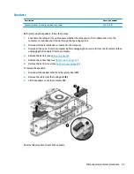
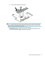
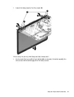
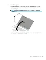
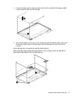
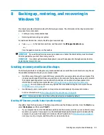
7.
Separate the display assembly from the computer (6).
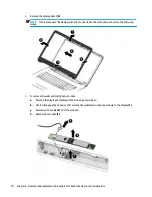
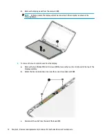
If it is necessary to replace any of the display assembly subcomponents:
1.
Flex the inside of the top edge (1), left and right sides (2), and the inside of the bottom edge (3) of the
display bezel until the bezel disengages from the display enclosure.
Component replacement procedures
69
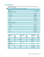
Summary of Contents for 17-x Series
Page 1: ...HP Notebook PC Intel Models HP 17 x000 17 x099 Maintenance and Service Guide ...
Page 4: ...iv Safety warning notice ...
Page 8: ...viii ...
Page 14: ...6 Chapter 1 Product description ...
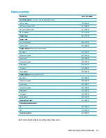
Page 29: ...Display assembly subcomponents Display assembly subcomponents 21 ...
Page 34: ...26 Chapter 3 Illustrated parts catalog ...
Page 68: ...60 Chapter 6 Removal and replacement procedures for Authorized Service Provider parts ...
Page 96: ...88 Chapter 8 Backing up restoring and recovering in Windows 10 ...
Page 102: ...94 Chapter 10 Specifications ...
Page 106: ...98 Chapter 11 Power cord set requirements ...
Page 108: ...100 Chapter 12 Recycling ...
Page 112: ...104 Index ...