background image

26

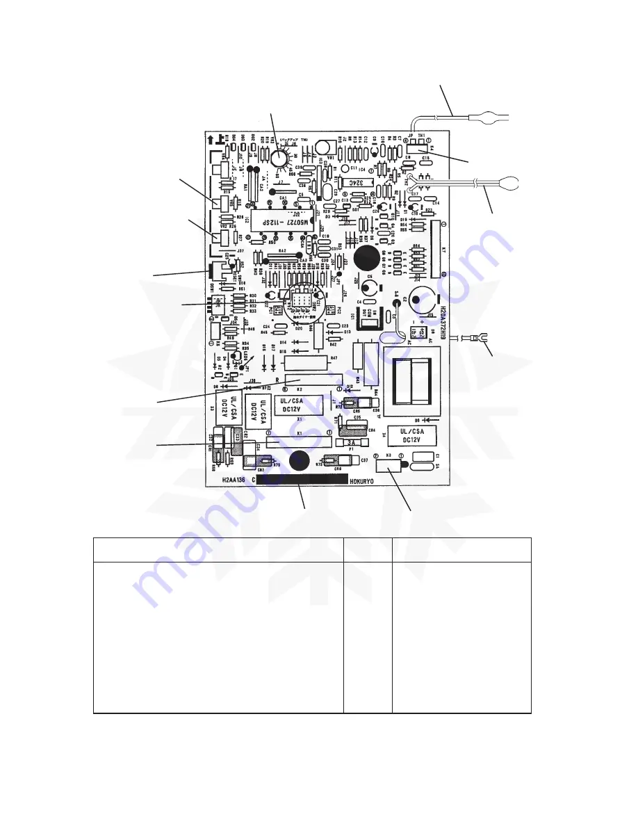
Thermistor (Cube Control)

Backup Timer VR3

Connector K4

Cube Control VR5

Defrost Control VR2

Thermistor
(Calibration)

*Not fitted on water-
 cooled models

Reset Switch

Water Supply Time
Setting Jumper
Wires

Signal Ground

Connector K2

Connector K1

ID Number

Connector K3

[a] CONTROLLER BOARD LAYOUT

Model

ID No.

Thermistor (Calibration)

IM-21CLE, IM-25LE, IM-25CLE, IM-30CLE

C10

Yes

IM-45LE, IM-45CLE-25, IM-65LE

IM-100LE, IM-130LE, IM-130ME, IM-160ME

C02

Yes

IM-25WLE, IM-30WLE, IM-45WLE, IM-65WLE

C12

No

IM-100WLE, IM-130WLE, IM-130WME

C03

No

IM-240ME, IM-240WME, IM-240M2E
IM-240WM2E

Summary of Contents for IM-100

Page 1: ... IM 25 IM 130 IM 30 IM 160 IM 45 IM 240 IM 65 SERVICE MANUAL Kälte Berlin Inh Christian Berg Am Pfarracker 41 12209 Berlin Fon 49 0 30 74 10 40 22 Fax 49 0 30 74 10 40 21 eMail info kaelte berlin de Internet http www kaelte berlin com Direktlink Hoshizaki Zylindereisbereiter IM130ME C zu Kälte Berlin ...

Page 2: ...r cooled 16 q IM 240WM2E Water cooled 17 II GENERALINFORMATION 18 1 CONSTRUCTION 18 a IM 25LE IM 45LE IM 65LE IM 100LE IM 130LE IM 130ME IM 160ME 18 b IM 21CLE IM 25CLE IM 30CLE 19 c IM 45CLE 25 20 d IM 100CLE 21 e IM 240ME IM 240M2E 22 f IM 25WLE IM 30WLE IM 45WLE IM 65WLE 23 g IM 100WLE IM 130WLE IM 130WME IM 240WME IM 240WM2E 24 2 CONTROLLER BOARD 25 a CONTROLLER BOARD LAYOUT 26 b BEFORE CHECKI...

Page 3: ...LE IM 130LE IM 130ME IM 160ME Air cooled 61 c IM 240ME Air cooled 62 d IM 240M2E Air cooled 63 e IM 25WLE IM 30WLE IM 45WLE IM 65WLE IM 100WLE IM 130WLE IM 130WME IM 240WME Water cooled 64 f IM 240MW2E Water cooled 65 2 WIRING DIAGRAM 66 a IM 21CLE IM 25LE IM 25CLE IM 30CLE IM 25WLE IM 30WLE 66 b IM 25L IM 25CL IM 25WL 67 c IM 45LE IM 45CLE 25 IM 45WLE 68 d IM 65LE IM 65WLE 69 e IM 65L IM 65WL 70 ...

Page 4: ...HOT GAS VALVE 106 7 WATER REGULATING VALVE WATER COOLED MODEL ONLY 107 a VALVE BODY 107 b WHOLE VALVE 107 8 WATER PAN ASSEMBLY 109 9 PUMP MOTOR 111 10 WATER VALVE 112 11 ACTUATOR MOTOR 113 12 CAM ARM 114 a CAM ARM A ACTUATOR MOTOR SIDE 114 b CAM ARM B REAR SIDE 114 13 ACTUATOR TOGGLE SWITCH 115 14 CONTROLLER BOARD 118 a MODIFICATION 118 b REPLACEMENT 118 15 THERMISTOR FOR CUBE CONTROL 120 16 SURGE...

Page 5: ...1 I SPECIFICATIONS 1 DIMENSIONS CONNECTIONS a IM 25LE Air cooled ...

Page 6: ...2 b IM 25CLE Air cooled Until March 2000 production Auxiliary Code K 1 ...

Page 7: ...3 c IM 21CLE IM 25CLE IM 30CLE Air cooled From April 2000 production Auxiliary Code K 2 ...

Page 8: ...4 d IM 45LE Air cooled ...

Page 9: ...5 e IM 45CLE 25 Air cooled ...

Page 10: ...6 f IM 65LE Air cooled ...

Page 11: ...7 g IM 100LE IM 130LE IM 130ME Air cooled ...

Page 12: ...8 h IM 100CLE Air cooled ...

Page 13: ...9 i IM 160ME Air cooled ...

Page 14: ...10 j IM 240ME Air cooled ...

Page 15: ...11 k IM 240M2E Air cooled ...

Page 16: ...12 l IM 25WLE IM 30WLE Water cooled ...

Page 17: ...13 m IM 45WLE Water cooled ...

Page 18: ...14 n IM 65WLE Water cooled ...

Page 19: ...15 o IM 100WLE IM 130WLE IM 130WME Water cooled ...

Page 20: ...16 p IM 240WME Water cooled ...

Page 21: ...17 q IM 240WM2E Water cooled ...

Page 22: ...nt Panel Lower Power Cord Water Tank Evaporator Water Plate Actuator Toggle Switch Bin Control Switch Water Valve Pump Motor Control Box Air cooled Condenser Fan Air Filter II GENERAL INFORMATION 1 CONSTRUCTION a IM 25LE IM 45LE IM 65LE IM 100LE IM 130LE IM 130ME IM 160ME ...

Page 23: ... Bin Condensing Unit Bin Door Front Panel Lower Water Tank Evaporator Water Plate Actuator Toggle Switch Bin Control Switch Water Valve Pump Motor Control Box Air cooled Condenser Fan Motor Air Filter Compressor b IM 21CLE IM 25CLE IM 30CLE ...

Page 24: ...ensing Unit Bin Door Front Panel Power Cord Water Tank Evaporator Water Plate Actuator Toggle Switch Bin Control Switch Water Valve Pump Motor Control Box Air cooled Condenser Fan Air Filter Compressor Actuator Motor c IM 45CLE 25 ...

Page 25: ...Actuator Toggle Switch Bin Control Switch Water Valve Pump Motor Control Box Air cooled Condenser Fan Air Filter Actuator Motor Top Panel Front Panel A Storage Bin Adjustable Leg Bin Door Front Panel B Power Cord Louver Handle Air Filter Front Panel C ...

Page 26: ...nt Panel Upper Storage Bin Condensing Unit Bin Door Front Panel Lower Power Cord Water Tank Evaporator Water Plate Actuator Toggle Switch Bin Control Switch Water Valve Pump Motor Control Box Air cooled Condenser Fan Air Filter Compressor ...

Page 27: ... Bin Condensing Unit Bin Door Front Panel Lower Power Cord Transformer Water Tank Evaporator Water Plate Actuator Toggle Switch Bin Control Switch Water Valve Pump Motor Control Box Condenser Fan Motor f IM 25WLE IM 30WLE IM 45WLE IM 65WLE ...

Page 28: ...Condensing Unit Bin Door Front Panel Lower Control Box Transformer Water Tank Evaporator Water Plate Actuator Motor Bin Control Switch Water Valve Pump Motor Compressor Condenser Hot Gas Valve g IM 100WLE IM 130WLE IM 130WME IM 240WME IM 240WM2E ...

Page 29: ... reverse side of the Controller Board and tiny electronic devices on it 4 Do not repair the electronic devices and parts on the Controller Board in the field Replace the whole board assembly when it fails 5 To get static free always touch the metal part of the icemaker before servicing Electrostatic Discharge will cause severe damage to the Controller Board 6 The Signal Ground Wire must be connect...

Page 30: ... Setting Jumper Wires Signal Ground Connector K2 Connector K1 ID Number Connector K3 a CONTROLLER BOARD LAYOUT Model ID No Thermistor Calibration IM 21CLE IM 25LE IM 25CLE IM 30CLE C10 Yes IM 45LE IM 45CLE 25 IM 65LE IM 100LE IM 130LE IM 130ME IM 160ME C02 Yes IM 25WLE IM 30WLE IM 45WLE IM 65WLE C12 No IM 100WLE IM 130WLE IM 130WME C03 No IM 240ME IM 240WME IM 240M2E IM 240WM2E ...

Page 31: ...ESET Reset Button To check the operation of the board push the Reset Button only during the freeze cycle Relay X1 Actuator Motor and Pump Motor X2 Hot Gas Valve and Fan Motor X3 Water Valve X4 Compressor Control VR2 Defrost Control VR3 Backup Timer VR5 Cube Control All the controls are factory adjusted Do not change setting except when replacing the board or if the setting has changed Refer to e C...

Page 32: ...ION Thermistor Sensor part is fragile glass sealed Handle with care Disconnect the Connector K4 on the board Remove the screw and the Thermistor Holder on the Evaporator Immerse the Sensor part in a glass containing ice and water for 5 minutes Check the resistance between K4 Connector Pins Replace the Thermistor in its correct position Connect K4 Manually set the Micro Switch in the TRIP and RESET...

Page 33: ...Thermistor detects defrost cycle finished IM 21 25 30 IM 100 130 IM 45 65 IM 160 240 X 4 ON X 4 ON X 1 2 OFF X 1 2 OFF X 3 OFF X 3 ON X 4 ON X 1 2 ON X 3 ON Actuator Toggle Switch moves to DEFROST position Hot Gas Valve opens IM 130_ 21 only Bin Control Switch tripped during defrost cycle X 4 OFF X 1 2 ON X 3 OFF 1 2 4 3 4 Adjustable 4 IM 21 25 30 IM 100 130 IM 45 65 IM 160 240 X 4 ON X 4 ON X 1 2...

Page 34: ...t check out each component that could result in an extended freezing time See guide below Lamp ON Water Plate open The Timer has stopped the machine because of an excessive defrost time See the guide below to check out the probable cause Lamp flashing ON OF If on the first cycle check out the Cam operation and or Toggle Switch If the machine has been in service for some time the Controller Board m...

Page 35: ...oken Defective Actuator Motor Cam Pin damaged Defective Cube Control Thermistor Clean or replace Replace Replace Replace Check for leak Replace Comp Starting Capacitor Replace Check for leak Replace Comp Starting Capacitor Replace Actuator Toggle Switch Replace Replace Replace Cam Pin and Cam Arm A Replace 1 2 3 4 5 6 1 2 3 1 2 3 4 5 Freeze Cycle Defrost Cycle Gas Leak 0V Hot Leak 0V Gas 100V Gas ...

Page 36: ... Cube Control using a miniature flat blade screwdriver CAUTION When adjusting the Variable Resistor VR5 for smaller dimple cubes it may be necessary to also increase the water supply time to melt away fragments of ice obstructing the Water Plate which could prevent cubes falling into the Bin 2 Backup Timer VR3 A backup timer is set to stop the freezing process when the freeze cycle time extends be...

Page 37: ... 20 20 20 20 C 30 40 40 35 30 10 C 60 80 60 90 40 4 Water Supply Control When adjusting the Variable Resistor VR5 Cube Control for smaller dimple cubes it may be necessary to adjust the water supply time setting as well following the instruction below Note 1 See II 2 a CONTROLLER BOARD LAYOUT for location of the Jumper Wires 2 Any adjustment will not be required under normal use If an insufficient...

Page 38: ...y hard water approx 250 ppm or more results in production of cloudy ice change the water supply time setting as follows Cut the jumper wire JE marked by arrow by a nipper Water supply time will be 60 sec when the Water Plate is closed The jumper wire JE for IM 240ME WME except IM 240M2E WM2E has already been cut at factory adjustment Normal setting 15 sec with Water Plate closed Controller Board M...

Page 39: ... 10 C Low Temp Condition RT Max 10 C 1 Employs dual speed fan motor control 2 Bimetal thermostat slows down fan motor rotation less airflow at low temperatures to prevent excessive condensation 3 5 of new refrigerant charge has been evaluated at RT 1 40 C 4 Reduced refrigerant charge less than half solves troubles with remaining refrigerant at low temperatures Control Box Bimetal Thermostat 21 3 C...

Page 40: ...d not be allowed in reach of the packaging elements plastic bags and expanded polystyrene as they are potential sources of danger CAUTION Remove shipping carton tape s and packing If packing material is left in the icemaker it will not work properly 1 After removing the packaging make sure that the icemaker is in good condition If in doubt please do not use the equipment 2 Remove shipping tape hol...

Page 41: ...4 Provided for Europe General G50 RINNAI only Adjustable Leg IM 100CLE 6 5 Remove shipping tape holding the Bin Control Switch by opening the Bin Door and reaching in see Fig 2 2 LOCATION WARNING 1 This icemaker is not intended for outdoor use Normal operating ambient temperature should be within 1 C to 40 C Normal operating water temperature should be within 5 C to 35 C Operation of the icemaker ...

Page 42: ...m to people animals or things for which the manufacturer cannot be held responsible Place the icemaker in the selected permanent site 4 ELECTRICAL CONNECTIONS WARNING THIS APPLIANCE MUST BE EARTHED This icemaker requires an earth that meets the national and local electrical code requirements To prevent possible severe electrical shock injury to individuals or extensive damage to equipment install ...

Page 43: ...oured Brown must be connected to the terminal which is marked with the letter L or coloured Red Should the socket outlets in the installation site not be suitable for the plug supplied with your product the plug must be removed cut off if it is moulded on plug and an appropriate plug fitted If the non rewirable plug has been cut from the power supply cord it must be disposed of There should be no ...

Page 44: ...essure exceeds 8 bar use a pressure reducing valve Do NOT throttle back the supply tap A plumbing permit and services of a licensed plumber may be required in some areas On water cooled models a back flow preventer may be required in the cooling water circuit Water should drain into an open trap The icemaker drain is gravity flow so ensure drain pipe has an adequate pitch or fall To prevent a back...

Page 45: ...and tightening as above It is a wise precaution to have a stop valve within easy reach 3 Hand tighten grey flexible outlet hose accessory onto the R3 4 fitting on the rear of the icemaker as indicated Fig 4 ensuring rubber sealing washer is correctly positioned to obtain a leak free joint The pipe can be cut to length as necessary to suit position of main drain Note Jointing compounds should be ap...

Page 46: ...a suitable sealing compound should be used to obtain a leak free joint 5 Use a pipe jointing compound for PVC to joint the outlet hose with PVC pipe accessory to the elbow as indicated Fig 8 The pipe can be cut to length as necessary to suit position of main drain Fig 6 Potable Water Inlet G3 4 Inlet Hose Drain Outlet Rc3 4 Outlet Hose Fig 7 Fig 8 Elbow 3 4 3 4 Nipple Outlet Hose PVC Pipe Elbow 3 ...

Page 47: ...e unit will be 5 to 6 m when the cooling water flows at the ratio of 4 to 5 lit min Select a Circulating Pump referring to the above values of heat flow Do not use a Cascade Pump or the Water Regulator will vary the flow and stop it during the defrost cycle The Strainer must be cleaned periodically Icemaker Connections 1 Attach the angled end of white flexible inlet hose accessory to the G3 4 fitt...

Page 48: ...and or a suitable sealing compound should be used to obtain a leak free joint Note Jointing compounds should be approved and suitable for potable water use 5 Connect the Condenser cooling circuit to the free ends of 1 2 3 4 nipples as indicated Fig 9 using a suitable rigid type pipe The opening pressure of the Water Regulator should be 7 bar The high side pressure during the defrost cycle will be ...

Page 49: ...outlet water temperatures will increase to 8 C with 60 water flow but the cooling capacity will decrease Be sure to keep enough capacity in summer Note When installing a Flow Control Valve as shown in Fig 10 the condition at the Cooling Water Inlet should not exceed the following ranges Water Temperature 30 C or less Water Pressure 0 5 bar or more Flow Rate 8 10 lit min b Connections according to ...

Page 50: ...ping connections been made 6 Has the power supply voltage been tested or checked against the nameplate rating Has a proper earth been installed to the icemaker 7 Has the water supply pressure been checked to ensure a minimum of 0 5 bar and maximum 8 bar 8 Have the Compressor hold down bolts and all refrigerant lines been checked against vibration and possible failure 9 Have the Bin Control Switch ...

Page 51: ...crease the risk of electrical short circuits and potential electrical shocks If in doubt disconnect the icemaker Do not pull the power cord in order to disconnect the icemaker from the feed network This appliance is not suitable for unsupervised use by young children or aged or infirm persons 3 All parts are factory adjusted Improper adjustments may result in failure 4 If the unit is turned off wa...

Page 52: ...water supply tap and remove the Inlet Hose 2 Remove the Front Panels Upper and Lower 3 Push the Reset Switch in the Control Box or disconnect power source and reconnect after 3 minutes 4 The Water Pan will open and then theActuator Toggle Switch will turn to the DEFROST position in 40 seconds Click sound will be heard 5 Blow out the water supply line immediately after the Water Pan has opened Note...

Page 53: ...ater Pan will open and then the Actuator Toggle Switch will turn to the DEFROST position in 40 seconds Click sound will be heard 7 Blow out the water supply line immediately after the Water Pan has opened Note This procedure is necessary to protect the icemaker from freezing up at subfreezing temperature 8 Unplug the icemaker with the Actuator Toggle Switch in the DEFROST position 9 Move the Tank ...

Page 54: ...pan 3 BIN CONTROL Bin Control Switch is mounted on the upper side of the Storage Bin This switch will turn off the unit automatically when the Storage Bin is full of ice Handle the Bin Control Switch carefully because the switch assembly is fragile Especially on removing ice do not touch or poke with a scoop Keep away from the Water Plate or Drain Pan to prevent jamming a BIN CONTROL SWITCH ASSEMB...

Page 55: ...to pull out the Switch Actuator Handle with care to prevent damage to the cam surface of the Actuator DETECTOR Push out the Detector holding the Switch Actuator c REASSEMBLING SWITCHACTUATOR Insert the lower Shaft and push it along the U Notch Check that the Switch Actuator moves free SWITCH BRACKET COVER Place the Switch Lever first and then attach the Switch in position Insert the guide and push...

Page 56: ...damp cloth containing a neutral cleaner to wipe off grease or dirt 2 Scoop and Storage Bin Handle Cleaning Sanitisation Daily 1 Either mix 3 litres of water with 11 ml of 5 25 sodium hypochlorite solution in a suitable container or the recommended Hoshizaki sanitiser as directed 2 Soak the Scoop in the solution for more than 3 minutes Rinse thoroughly and shake to remove surplus liquid Note Using ...

Page 57: ... the metal parts Always rinse the sanitiser unless directed otherwise by Hoshizaki guidelines 4 Air Filter Air Cooled Model Only A plastic mesh Air Filter is fitted to remove dirt or dust from the air preventing the Condenser from getting clogged As the Filter becomes dirty air circulation through the Condenser will be reduced affecting the icemaker s performance Remove and clean the Air Filter at...

Page 58: ...Top Panel and Front Panel Upper 4 Disconnect the Inlet Hose from the Water Valve 5 Remove the Mesh Filter from the Water Valve 6 Clean the Mesh using a brush 7 Replace the Mesh and Inlet Hose in their correct positions 8 Open the water supply tap 9 Plug in the icemaker or connect the power source 10 Check for leaks 11 Replace the panels in their correct positions ...

Page 59: ...with water 2 Remove the panels and check for leaks from the water line 3 Unplug the icemaker or disconnect the power source and close the water supply tap 4 Disconnect the cooling water inlet and outlet pipings and attach fittings to connect hoses 5 Disconnect the inlet and outlet tubings of the Water Regulator and replace the Water Regulator by fittings 6 Connect hoses as shown in Fig 18 and secu...

Page 60: ...tely 6 Do not use any ammonia type cleaners on any part of the icemaker 7 When the ambient and water temperatures are 10 C or below the Water Pan may remain open Warm the icemaking compartment up to 20 C around the Thermistor 8 Be sure to follow the cleaning and sanitizing instructions below 1 Use a suitable container to dilute the cleaner Nickel Safe Ice Machine Cleaner by The Rectorseal Corporat...

Page 61: ...ease the Bin Control Switch into the running position See Fig 20 The icemaker will restart in 80 seconds and the Water Pan will start to open 8 Close the water supply tap 9 After the ice has dropped and the Water Pan begins to close move the Washing Switch on the bottom IM 21 25 30CLE only or right side except IM 21 25 30CLE of the Control Box to the WASH position See Fig 21 Except IM 21 25 30 100...

Page 62: ...r IM 100 130 160 Mix 30 ml of the sodium hypochlorite solution with 7 6 litres of water IM 240 Mix 44 ml of the sodium hypochlorite solution with 11 4 litres of water Alternatively use the Hoshizaki recommended sanitizer as directed by the relevant instructions 15 Repeat the above steps 5 6 and 7 and close the water supply tap 16 As soon as the Water Pan closes pour the sanitizing solution prepare...

Page 63: ...cleaning as detailed in V 1 3 IMPORTANT Be sure to operate the Bin Control Switch as specified in 11 and 17 within 40 minutes after the Water Pan closes After 40 minutes pass the interlock will operate to stop the icemaker It will not reset automatically If the interlock should operate disconnect the power source and then reconnect it ...

Page 64: ...ccumulator Bin Controller Board Hot Gas Valve Compressor Condenser Drier Fan Water Circuit Refrigeration Circuit Insulation Insulation VI TECHNICAL INFORMATION 1 WATER CIRCUIT AND REFRIGERANT CIRCUIT a IM 21CLE IM 25LE IM 25CLE IM 30CLE IM 45LE IM 45CLE 25 IM 65LE Air cooled ...

Page 65: ...ter Pan Evaporator Controller Board Hot Gas Valve Compressor Condenser Drier Fan Water Circuit Refrigeration Circuit Water Pump Thermistor Expansion Valve Bulb b IM 100LE IM 100CLE IM 130LE IM 130ME IM 160ME Air cooled ...

Page 66: ...led Water Valve Water Pump Water Pan Controller Board Pressure Switch Thermistor Expansion Valve Drier Condenser Expansion Valve Bulb Strainer Hot Gas Valve Compressor Water Circuit Refrigerant Circuit Evaporator Fan Motor ...

Page 67: ...oled Water Valve Water Pump Water Pan Controller Board Pressure Switch Thermistor Expansion Valve Drier Condenser Expansion Valve Bulb Strainer Hot Gas Valve Compressor Water Circuit Refrigerant Circuit Evaporator Fan Motor ...

Page 68: ...d Hot Gas Valve Compressor Condenser Water Circuit Refrigeration Circuit Water Pump Thermistor Expansion Valve Bulb Drier Strainer Pressure Switch e IM 25WLE IM 30WLE IM 45WLE IM 65WLE IM 100WLE IM 130WLE IM 130WME IM 240WME Water cooled Water Regulator ...

Page 69: ...er cooled Water Inlet Water Pan Evaporator Controller Board Hot Gas Valve Compressor Condenser Water Circuit Refrigeration Circuit Water Pump Thermistor Expansion Valve Bulb Drier Strainer Pressure Switch Water Regulator ...

Page 70: ...66 2 WIRING DIAGRAM a IM 21CLE IM 25LE IM 25CLE IM 30CLE IM 25WLE IM 30WLE ...

Page 71: ...67 b IM 25L IM 25CL IM 25WL ...

Page 72: ...68 c IM 45LE IM 45CLE 25 IM 45WLE ...

Page 73: ...69 d IM 65LE IM 65WLE ...

Page 74: ...70 e IM 65L IM 65WL ...

Page 75: ...71 f IM 100LE IM 100CLE IM 100WLE Note The Washing Switch is provided only after the Auxiliary Code H 0 ...

Page 76: ...72 g IM 130LE IM 130WLE Note The Washing Switch is provided only after the Auxiliary Code H 0 ...

Page 77: ...73 h IM 130LE 21 IM 130WLE 21 Note The Washing Switch is provided only after the Auxiliary Code H 0 ...

Page 78: ...74 i IM 130ME IM 130WME Note The Washing Switch is provided only after the Auxiliary Code H 0 ...

Page 79: ...75 j IM 130ME 21 IM 130WME 21 Note The Washing Switch is provided only after the Auxiliary Code H 0 ...

Page 80: ...76 k IM 160ME ...

Page 81: ...77 l IM 240ME IM 240WME ...

Page 82: ...78 m IM 240M2E IM 240WM2E ...

Page 83: ...ze Cycle Time min 12 5 17 24 32 Defrost Cycle Time min 6 4 2 5 2 Water Consumption lit h 6 2 5 4 4 3 3 4 Electric Consumption W 240 240 280 300 IM 25LE 50Hz Head Pressure peak bar 6 9 12 5 14 5 Ice Production kg d 23 19 16 12 Freeze Cycle Time min 10 11 5 15 5 20 5 Defrost Cycle Time min 4 3 2 2 Water Consumption lit h 8 2 7 9 6 6 5 2 Electric Consumption W 240 240 280 300 IM 25LE 25 50Hz Head Pre...

Page 84: ...e Time min 10 13 17 27 Defrost Cycle Time min 3 5 3 2 2 Water Consumption lit h 8 6 7 2 6 1 4 Electric Consumption W 240 250 270 280 IM 30CLE 25 50Hz Head Pressure peak bar 6 8 12 13 Ice Production kg d 32 30 28 26 Freeze Cycle Time min 12 13 5 14 5 16 3 Defrost Cycle Time min 3 2 5 2 5 2 Water Consumption lit h 7 6 7 2 6 7 6 3 Electric Consumption W 235 235 245 340 IM 30WLE 50Hz Head Pressure med...

Page 85: ...3 27 Defrost Cycle Time min 4 5 3 2 5 2 Water Consumption lit h 9 4 8 8 7 6 6 7 Electric Consumption W 310 340 360 390 IM 45LE 25 60Hz Head Pressure peak bar 5 5 9 12 5 15 5 Ice Production kg d 47 45 42 39 Freeze Cycle Time min 15 16 5 18 20 Defrost Cycle Time min 3 5 3 2 5 2 Water Consumption lit h 12 5 11 7 11 3 10 4 Electric Consumption W 270 280 295 315 IM 45WLE 50Hz Head Pressure median bar 1...

Page 86: ...6 2 18 5 20 3 22 Defrost Cycle Time min 3 3 5 3 2 Water Consumption lit h 15 4 13 8 12 9 12 5 Electric Consumption W 380 390 400 420 IM 65WLE 50Hz Head Pressure median bar 9 9 9 9 Ice Production kg d 51 54 50 48 Freeze Cycle Time min 23 5 22 5 25 26 Defrost Cycle Time min 3 2 5 2 2 Water Consumption lit h 9 6 10 2 9 4 9 1 Electric Consumption W 465 475 480 500 IM 65WLE 60Hz Head Pressure median ba...

Page 87: ...25 31 5 Defrost Cycle Time min 4 2 5 2 2 Water Consumption lit h 31 6 18 8 13 5 10 9 Electric Consumption W 620 630 700 760 IM 100LE 23 60Hz Head Pressure peak bar 7 10 5 15 18 Ice Production kg d 98 95 87 75 Freeze Cycle Time min 11 12 5 14 5 17 2 Defrost Cycle Time min 4 2 5 2 2 Water Consumption lit h 52 4 29 6 20 17 3 Electric Consumption W 600 610 630 680 IM 100LE 21 50Hz Head Pressure peak b...

Page 88: ...15 5 20 24 27 5 Defrost Cycle Time min 3 5 2 5 2 2 Water Consumption lit h 35 4 19 8 12 8 11 2 Electric Consumption W 660 670 690 720 IM 130LE 50Hz Head Pressure peak bar 10 5 14 17 5 21 Ice Production kg d 100 90 76 70 Freeze Cycle Time min 13 17 20 5 22 5 Defrost Cycle Time min 3 5 2 2 2 Water Consumption lit h 40 8 17 4 14 7 13 5 Electric Consumption W 530 535 540 565 IM 130LE 23 50Hz Head Pres...

Page 89: ...10 12 14 5 18 Defrost Cycle Time min 3 5 2 5 2 2 Water Consumption lit h 46 4 30 7 20 16 6 Electric Consumption W 610 650 700 710 IM 130ME 21 50Hz Head Pressure peak bar 13 17 21 23 Ice Production kg d 125 112 105 100 Freeze Cycle Time min 14 5 17 5 19 5 21 Defrost Cycle Time min 4 3 2 5 2 Water Consumption lit h 42 5 30 4 23 3 14 4 Electric Consumption W 580 590 610 650 IM 130WME 50Hz Head Pressu...

Page 90: ...14 3 Defrost Cycle Time min 3 5 3 2 5 2 Water Consumption lit h 32 1 24 6 20 4 17 3 Electric Consumption W 1450 1500 1600 1640 IM 240ME 21 60Hz Head Pressure peak bar 16 3 17 8 23 3 26 3 Ice Production kg d 240 230 210 185 Freeze Cycle Time min 12 5 15 3 18 6 21 4 Defrost Cycle Time min 5 5 3 5 2 2 Water Consumption lit h 42 25 2 14 3 12 Electric Consumption W 1120 1200 1330 1450 IM 240M2E 50Hz He...

Page 91: ...Defrost Cycle Time min 3 5 3 2 5 2 Water Consumption lit h 30 4 24 6 17 1 14 1 Electric Consumption W 1250 1250 1300 1300 IM 240WME 23 50Hz Head Pressure median bar 19 19 19 19 Ice Production kg d 190 185 175 160 Freeze Cycle Time min 13 7 14 7 16 2 18 4 Defrost Cycle Time min 3 5 3 2 5 2 Water Consumption lit h 26 9 22 8 18 3 13 8 Electric Consumption W 1430 1450 1500 1550 IM 240WME 23 60Hz Head ...

Page 92: ...6 2 18 4 Defrost Cycle Time min 3 5 3 2 5 2 Water Consumption lit h 26 9 22 8 18 3 13 8 Electric Consumption W 1430 1450 1500 1550 IM 240WM2E 23 60Hz Head Pressure peak bar 19 4 19 4 19 5 20 Ice Production kg d 215 207 195 180 Freeze Cycle Time min 10 10 10 8 12 4 Defrost Cycle Time min 3 5 3 2 5 2 Water Consumption lit h 31 7 27 1 23 18 3 Electric Consumption W 1250 1250 1300 1300 IM 240WM2E 21 5...

Page 93: ...5 4 5 5 5 IM 160ME Evaporator Inlet Temp C 20 18 17 16 Suction Pressure Peak bar 3 0 3 5 4 0 4 5 IM 240ME IM 240M2E Evaporator Inlet Temp C 20 18 16 14 60Hz Ambient Temp C 10 21 32 38 MODEL Water Temp C 10 15 21 32 Suction Pressure Peak bar 1 0 1 0 1 5 1 5 IM 25L Evaporator Inlet Temp C 16 16 15 14 Suction Pressure Peak bar 1 0 1 5 2 0 2 5 IM 45LE Evaporator Inlet Temp C 16 16 14 10 Suction Pressu...

Page 94: ...IM 240WME IM 240WM2E Evaporator Inlet Temp C 20 18 16 14 60Hz Ambient Temp C 10 21 32 38 MODEL Water Temp C 10 15 21 32 Suction Pressure Peak bar 1 0 1 5 2 0 2 0 IM 25WL Evaporator Inlet Temp C 20 20 19 18 Suction Pressure Peak bar 1 5 2 0 2 0 3 0 IM 45WLE Evaporator Inlet Temp C 16 16 15 14 Suction Pressure Peak bar 1 0 1 5 2 0 2 5 IM 65WLE Evaporator Inlet Temp C 19 18 16 15 Suction Pressure Pea...

Page 95: ...Timer operates 1 See II 2 b BEFORE CHECKING CONTROLLER BOARD i Hot Gas Solenoid Valve 1 Continues to open in freeze cycle and High Temperature Safety Backup Timer operates 1 Check for power OFF in freeze cycle and replace 1 Water supply OFF and water supply cycle does not finish 1 Check for recommended pressure j Water Supply Line water cooled 2 Condenser water pressure too low or OFF and Pressure...

Page 96: ...gged 1 Clean 3 Compressor runs but other components will not start a Control Circuit 1 Loose connection or broken wire 1 Repair or replace a Wiring 1 Loose connection or broken wire 1 Repair or replace b Actuator Toggle Switch 1 Defective 1 Replace 4 Fan Motor will not run c Thermistor Controller Board 1 See II 2 CONTROLLER BOARD a Water Solenoid Valve 1 Diaphragm does not close 1 Check for water ...

Page 97: ...efrigerant 2 Air or moisture trapped 2 Replace Drier and recharge b Compressor 1 Defective valve 1 Replace Compressor c Hot Gas Solenoid Valve 1 Continues to open in freeze cycle 1 Check and replace 7 All components run but no ice is produced d Expansion Valve 1 Continues to close in freeze cycle 1 Check and replace a Wiring 1 Loose connection or broken wire 1 Repair or replace b Actuator Toggle S...

Page 98: ...aks e Refrigerant Circuit 1 Excessive moisture 1 Replace Drier and recharge correctly f Thermistor Controller Board 1 See II 2 CONTROLLER BOARD 1 Freeze cycle time is too long g Air Filter Condenser 1 Clogged 1 Clean a Evaporator 1 Scaled up 1 Clean or remove scale b Refrigerant Charge 1 Undercharged 1 Check for leaks and recharge correctly c Hot Gas Valve 1 Defective 1 Replace d Thermistor Contro...

Page 99: ...pressure a Water Supply Line 2 Clogged 2 Check Strainer and clean 1 High hardness or contains impurities 1 Install a water filter or scale treatment b Water Quality 2 Lime is deposited inside Cooling Water Tubing 2 Clean c Water Valve 1 Clogged 1 Clean d Water System 1 Scaled up 1 Clean or remove scale e Water Plate 1 Jet hole clogged 1 Clean 1 Leaks 1 Replace 2 Bearings worn out 2 Replace f Pump ...

Page 100: ...rs worn out 1 Replace 1 Bearings worn out 1 Replace 2 Fan Blade deformed 2 Replace Fan Blade c Fan Motor 3 Fan Blade does not move freely 3 Replace d Compressor 1 Mounting pad out of position 1 Reinstall 2 Abnormal noise e Refrigerant Lines 1 Rubbing or touching on other surfaces 1 Secure or reset pipes 3 Ice in Storage Bin often melts a Bin Drain 1 Plugged 1 Clean a Bimetal Thermostat 1 Defective...

Page 101: ... follows 1 Remove the Cap Nut 2 Rotate the Adjust Screw 3 Watch holes of ice cubes produced Standard setting is that Evaporator inlet side and outlet side cubes have almost the same diameters To make the inlet side larger rotate 90 180 clockwise Smaller counterclockwise Do not rotate more than 180 at a time CAUTION Overadjustmentofthevalvemayresultinliquidrefrigerantreturncausingfreezing to the su...

Page 102: ...pressure gauge to high side line or prepare a thermometer to check Condenser drain temperature 2 Rotate the Adjust Screw using a flat blade screwdriver so that the pressure gauge shows 10 bar IM 25WLE IM 30WLE IM 45WLE IM 65WLE IM 100WLE 16 bar IM 130WLE IM 130WME or 19 bar IM 240WME IM 240WM2E or the thermometer reads 38 40 C 5 minutes after Freeze Cycle starts When the pressure or temperature ex...

Page 103: ...ux R134a R404A Repair of the refrigerant circuit needs brazing It is no problem to use the same handy flux that has been used for the current refrigerants However its entrance into the refrigerant circuit should be avoided as much as possible 4 Oil for Processing of Copper Tubing R134a R404A When processing the copper tubing for service wipe off oil if any used by using alcohol or the like Do not ...

Page 104: ...tector Do not use air or oxygen instead of nitrogen for this purpose or rise in pressure as well as in temperature may cause R22 R134a or R404A to suddenly react with oxygen and explode Be sure to use nitrogen to prevent explosion b REFRIGERANT RECOVERY The refrigerant must be recovered if required by an applicable law No refrigerant Access Valve is provided in the unit Install a properAccess Valv...

Page 105: ...gh side Valve on the Gauge Manifold and accurately measure in the liquid charge Close the valve on the Charging Cylinder before closing the High side Manifold Valve Any remaining liquid in the line can be charged into the low side Note Always charge in the liquid stage as many refrigerants are blends and vapour charging will affect the blend consistency eg R404A 7 Turn on the icemaker Release the ...

Page 106: ... with an abrasive cloth paper 10 Place the Compressor in position and secure it using the Bolts and Washers 11 Remove Plugs from the Compressor Suction and Discharge Pipes 12 Braze or solder the Access Suction and Discharge lines Do not change this order with nitrogen gas flowing at a pressure of 0 2 0 3 bar 13 Install the new Drier See 3 DRIER 14 Check for leaks using nitrogen gas 10 bar and soap...

Page 107: ...t 6 Braze or solder the new Drier with the arrow on the Drier in the direction of the refrigerant flow Use nitrogen gas at a pressure of 0 2 0 3 bar when brazing tubings Braze in an Access Valve using a tee if necessary 7 Check for leaks using nitrogen gas 10 bar and soap bubbles 8 Evacuate the system and charge it with refrigerant See 1 c EVACUATION AND RECHARGE 9 Replace the Rear Mesh in its cor...

Page 108: ...ing equipment Protect the Evaporator and pipes from excessive heat with damp cloths or similar 5 Remove the Expansion Valve Sensor Bulb 6 Remove the Drier using brazing equipment 7 Braze in the new Expansion Valve Protect the body of the valve from excessive heat and use nitrogen at a pressure of 0 2 0 3 bar when brazing 8 Braze or solder the new Drier See 3 DRIER 9 Check for leaks using nitrogen ...

Page 109: ... referring to 8 WATER PAN ASSEMBLY 5 Disconnect the solder connections on the Evaporator using brazing equipment Protect the Expansion Valve from excessive heat 6 Remove the four nuts holding the Evaporator 7 Install the new Evaporator and secure it with the Bolts Collars Spacer and Nuts 8 Remove and replace the Drier See 3 DRIER 9 Braze pipes with nitrogen gas flowing at a pressure of 0 2 0 3 bar...

Page 110: ...the Solenoid Coil 6 Remove the valve and Drier using brazing equipment 7 Braze the new Hot Gas Valve with nitrogen gas flowing at a pressure of 0 2 0 3 bar WARNING Always protect the valve body by using a damp cloth to prevent the valve from overheating Do not braze with the valve body exceeding 120 C 8 Install the new Drier See 3 DRIER 9 Check for leaks using nitrogen gas 10 bar and soap bubbles ...

Page 111: ...t Panel and Louver in their correct positions 11 Plug in the icemaker or connect the power source b WHOLE VALVE IMPORTANT Always install a new Drier every time the sealed refrigeration system is opened Do not replace the Drier until after all other repair or replacement has been made 1 Unplug the icemaker or disconnect the power source 2 Close the water supply tap 3 Remove the Front Panel Lower Lo...

Page 112: ...the new valve and insert the Capillary Tubes into the Copper Tube 10 Web the Copper Tube end and braze or solder the Copper Tube and Capillary Tubes together 11 Install the new Drier See 3 DRIER 12 Check for leaks using nitrogen gas 10 bar and soap bubbles 13 Evacuate the system and charge it with refrigerant See 1 c EVACUATION AND RECHARGE 14 Connect the flare connections 15 Open the water supply...

Page 113: ...ove the two Extension Springs from the Cam Arms 6 Remove the Water Plate Bracket and the Water Pan Assembly 7 Remove the two Spring Hook Screws from the Water Tank 8 Remove the screws and the Water Plate Bracket 9 Remove the Pump Suction and Discharge Tubings 10 Remove the Pump Motor Bracket from the Water Plate 11 Install the new Water Plate or Water Tank in the reverse order of the removal proce...

Page 114: ...PTION 1 Water Plate 2 Water Tank 3 Water Plate Bracket 4 Drain Guide 5 Pump Motor Bracket 6 Friction Plate 7 Spring Hook Screw 8 Pump Tubing Suction 9 Pump Tubing Discharge 10 Clamp nylon tie 11 Water Pump Assembly 12 U Packing ...

Page 115: ...sconnect the Pump Suction and Discharge Tubings 6 Disassemble the Pump Motor and check the Motor or parts 7 Install the new motor or parts in the reverse order of the removal procedure 8 Plug in the icemaker or connect the power source and check for leaks 9 Replace the panels in their correct positions INDEX NO DESCRIPTION 1 Pump Motor 2 Retainer 3 Mechanical Seal 4 O ring 5 Fixing Plate for O rin...

Page 116: ...alve Outlet tubing by releasing the Clamp 6 Remove the Inlet Hose and Water Valve 7 Install the new valve in the reverse order of the removal procedure 8 Open the water supply tap 9 Plug in the icemaker or connect the power source 10 Check for leaks 11 Replace the Top Panel in its correct position Note When replacing parts disassemble as shown in Fig 17 page 54 and replace the defective parts ...

Page 117: ...nnect the Actuator Motor leads in the Wiring Channel 6 Remove the Actuator Motor Bracket 7 Remove the Spring Pin securing the Shaft to the Cam Arm 8 Remove the Actuator Motor 9 Install the new Actuator Motor in the reverse order of the removal procedure 10 Check and adjust so that the Cam Arm normally moves the Actuator Toggle Switch to the FREEZE and DEFROST positions See II 2 b BEFORE CHECKING C...

Page 118: ...d push the Reset Switch on the Control Box to open the Water Pan 3 Unplug the icemaker or disconnect the power source 4 Remove the Extension Spring from the Cam Arm B 5 Remove the Split Pin from the Cam Shaft 6 Remove the Cam Arm B 7 Install the new Cam in the reverse order of the removal procedure 8 Replace the panels in their correct positions 9 Plug in the icemaker or connect the power source ...

Page 119: ...ding the Actuator Toggle Switch 4 Cut off the Nylon Tie holding the Vinyl Cover Bag 5 Disconnect the Receptacle of the leads 6 Install the new Actuator Toggle Switch in the reverse order of the removal procedure Note Be sure to secure the Vinyl Cover Bag 7 Replace the panels in their correct positions 8 Plug in the icemaker or connect the power source ...

Page 120: ...116 Fig 30 ...

Page 121: ...tuator Motor 2 Actuator Motor Bracket 3 Cam Arm A 4 Cam Arm B 5 Cam Shaft 6 Extension Spring 7 Actuator Toggle Switch 8 Switch Washer 9 Switch Cover 10 Cam Shaft Bearing 11 Bearing A 12 Bearing B 13 Collar Spacer 14 Bolt 15 Pin A 16 Washer 17 Pin B 18 Base 19 Insulation 20 Thermistor Holder 21 Thermistor Cube Control ...

Page 122: ...oard referring to the Instruction Sheet attached b REPLACEMENT 1 Unplug the icemaker or disconnect the power source 2 Remove the Front Panel Lower except IM 21 25 30CLE 3 Remove screws and the Control Box Cover 4 Pull the Shield Plate slightly toward you and disconnect the Signal Ground wire 5 Pull out the Controller Board half way and disconnect the Connectors K1 K2 K3 and K4 6 Pull out and remov...

Page 123: ...e Do not cut off Bushing Base Signal Ground Wire Shield Plate Controller Board Fuse Holder Control Box Cover Bushing Nylon Tie Do not cut off Controller Board Shield Plate Control Box IM 21 25 30CLE only Except IM 21 25 30CLE Signal Ground Wire ...

Page 124: ...K4 on the Controller Board referring to 14 b REPLACEMENT 4 Unscrew and remove the Thermistor Holder and Thermistor located on the Evaporator Front Side 5 Install the new thermistor in the reverse order of the removal procedure by using a sealant High thermal Conduct Type See Fig 32 Note Recommended sealant is KE4560RTV manufactured by SINETSU SILICON When other type of sealant used the cube size a...

Page 125: ... Remove two screws at the front bottom of the Control Box and remove the Control Box Cover 4 Remove the Quick Disconnect Terminal from the Surge Absorber 5 Remove the screw securing the Surge Absorber 6 Remove the Surge Absorber 7 Install the new Surge Absorber in the reverse order of the removal procedure Note Function of Surge Absorber By passes a surge coming through the power supply line cause...

Page 126: ...the surrounding space does not allow a tilt to the right 2 Unscrew and remove the Front Panel Lower and Fan Motor Guard 3 Cut the clamped ends closed end connectors of the Fan Motor leads near the Compressor terminal Uncoat the cut lead ends with a wire stripper 4 Remove the hexagon bolt securing the Fan Motor Bracket Front 5 Lift up the left side of the icemaker and hold it in position using a sp...

Page 127: ...or Bracket Condenser Securing Bolt Front Front Refrigeration Circuit Top View Fig 35 CAUTION Keep the leads away from any moving parts ex fan hot parts and sharp edges 10 Replace the Fan Motor Guard and Front Panel Lower in their correct positions and fix them with the machine screws 11 Push the icemaker back in position if it has been pulled out for service Plug in the icemaker or connect the pow...

Page 128: ...e securing bolt of the Fan Motor Bracket Rear hold the icemaker in position using a spacer at the bottom to prevent overturn 2 Tighten the securing bolts with a spanner or the like 3 The securing bolts for the Fan Motor Brackets are different in length Do not mix them up See Fig 37 4 Do not let the Fan Blade edges touch the Condenser Air Board or other parts 5 Fit the U Nut in the proper direction...

Page 129: ...HOSHIZAKI EUROPE LTD UNIT A STAFFORD PARK 18 TELFORD SHROPSHIRE TF3 3DJ ENGLAND PHONE 01952 291777 ...

Reviews: