background image


SW600 Owner’s Manual – Version 1.2 07/2018                          

  47


  www.horsch.com 

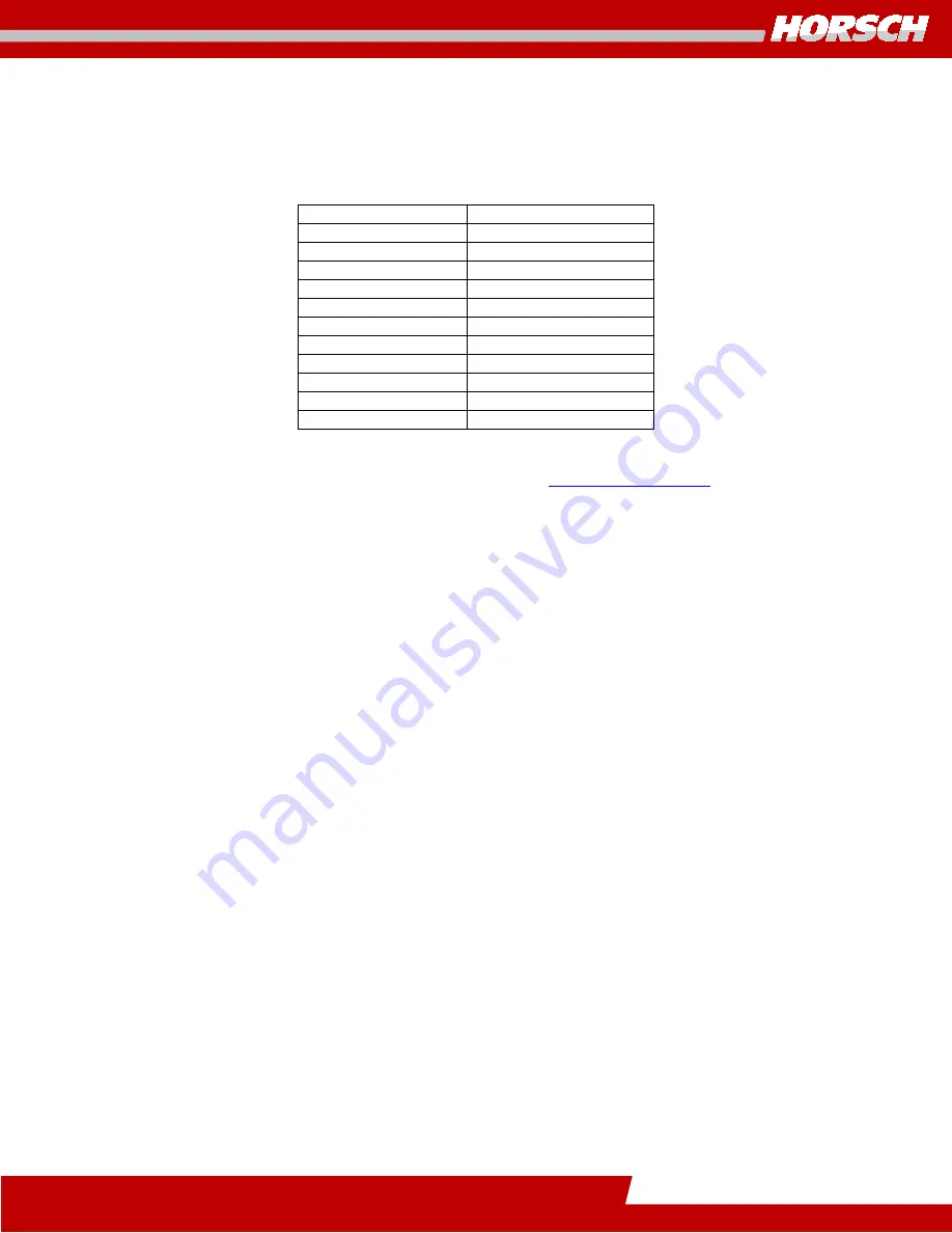
Undercarriage & Track System Specifications 


Trailed Track System (SW600) 
 

Model 

36” x 236” 

Capacity 

35 Ton 

Width 

36”  

Length 

103.5” 

Surface Area 

2425 in

 per track 

Total Idlers/Track 

Idler Diameter 

36”  

Total Bogie/Track 

Bogie Diameter 

16”  

Approx. Weight 

9,000 lbs. (4090 kg) 

Pressure Required 

1500 PSI 

Ground Pressure 

12 PSI 


*For further information on the track system see 

Trailed Track System

 in this manual. 


Summary of Contents for SW 600

Page 1: ...Seed Wagon Issued February 2017 Owner s Manual Serial Numbers SW600 SN 230060017001 Current SW 600...

Page 2: ...2 SW600 Owner s Manual Version 1 2 07 2018 www horsch com...

Page 3: ...SW600 Owner s Manual Version 1 2 07 2018 3 www horsch com...

Page 4: ...ve Clothing 20 Information Regarding Safety 21 Safety Symbols on the Machine 22 Use for the Intended Purpose 33 Operational Safety 33 Road Traffic Safety 35 Hydraulic System 36 Hydraulic Function Prec...

Page 5: ...ing Unit w Electric Motor 55 Rotors for Various Grain Types 55 Meter Roller Alignment 56 Roller Seed Rate Chart 57 Roller Replacement 60 Roller Replacement with Full Tank 61 Assembly Instructions 62 F...

Page 6: ...8 Weekly Maintenance or every 50 working hours 79 Monthly Maintenance or every 100 working hours 79 Annual Maintenance or every 500 working hours 80 Every 5 years or 2000 working hours 80 Off Season S...

Page 7: ...SW600 Owner s Manual Version 1 2 07 2018 7 www horsch com Seed Transfer 94 Metering System 95 Faults Remedies 96 Support 97 Notes 98 Index 99...

Page 8: ...ht hand and left hand are determined by facing the direction of forward travel respectively HORSCH reserves the right to alter illustrations as well as technical data and weights contained in this man...

Page 9: ...ve been completed correctly and submitted no later than four weeks after the damage occurred No warranty claims will be accepted to machines under the warranty waiver start date except any related Tec...

Page 10: ...10 SW600 Owner s Manual Version 1 2 07 2018 www horsch com...

Page 11: ..._______________________ Name of the Service Technician Dealer representative Dealer Customer Name ______________________________ Name _______________________________________ Address __________________...

Page 12: ...12 SW600 Owner s Manual Version 1 2 07 2018 www horsch com...

Page 13: ...______________________ Name of the Service Technician Dealer representative Dealer Customer Name ______________________________ Name _______________________________________ Address ___________________...

Page 14: ...14 SW600 Owner s Manual Version 1 2 07 2018 www horsch com...

Page 15: ...______________________ Name of the Service Technician Dealer representative Dealer Customer Name ______________________________ Name _______________________________________ Address ___________________...

Page 16: ...16 SW600 Owner s Manual Version 1 2 07 2018 www horsch com...

Page 17: ...of all safety precautions that must be observed when transporting the machine in field and on public roads When the machine is transported on a road or highway at night or during the day accessory lig...

Page 18: ...18 SW600 Owner s Manual Version 1 2 07 2018 www horsch com...

Page 19: ...Number Tag reference picture below on the machine with the above mentioned information It is located on the main frame cross member tube directly behind the front hitch just off center towards the lef...

Page 20: ...rm other users of the warnings and safety instructions and the location of this Owner s Operators Manual Do not carry out any operations which may affect the safe use of the machine Authorized Operato...

Page 21: ...Information Regarding Safety The following warnings and safety instructions apply to all sections in these operating instructions All users must follow recommended precautions and safe operating pract...

Page 22: ...e is a risk of crushing as long as parts could still be moving Watch out for fluids spraying out under high pressure follow the operating instructions It is only permitted to remain in the danger zone...

Page 23: ...pair the function and or safety and affect the machine life and thus void the Warranty Operate Safely Do not make field adjustments while machine is in motion Do not enter tank unless another person i...

Page 24: ...gnal Person Always have the signal person stand in clear view Be sure signal person stays a safe distance away from the machine when it is moving Prior to starting the tractor discuss hand signals and...

Page 25: ...c hoses before removing shields for adjustment or service Use a Safety Chain A safety chain will help control drawn equipment should it accidentally separate from the drawbar of the tractor A safety c...

Page 26: ...sions between motorist and slow moving equipment on public roads Frequently check for traffic from the rear especially in turns and use the turn signals where necessary Always use the flashing warning...

Page 27: ...her bystanders when mixing with seed or when filling the tank Wear a filtered respirator if you cannot avoid dust Wear goggles to protect your eyes Wash exposed skin areas frequently Do not leave pest...

Page 28: ...s Never jump on or off the machine Never mount or dismount a moving machine Do not ride on the machine Do not stand on the tanks or catwalk Keep Riders off Machines Keep riders off the machine at all...

Page 29: ...self propelled machines on public roads Frequently check for traffic from the rear especially in turns use turn signals where necessary Use headlight flashing warning lights and turn signals day and n...

Page 30: ...and travel at a reduced speed Reducing the speed maximizes stability and control and the tractors braking capability Use engine braking to reduce speed if available Avoid sharp turns or rapid steerin...

Page 31: ...n good operating condition and properly installed Fix damaged areas immediately Replace worn or broken items with OEM replacement parts from your authorized dealer Remove any buildup of grease oil and...

Page 32: ...medical attention immediately Any fluid injected into the skin must be surgically removed within a few hours or serious illness may result Medical examiners unfamiliar with this type of injury should...

Page 33: ...ect on specific design features of the machine and affect the safety of machine operators and the machine itself HORSCH will accept no liability for damage resulting from improper use The risk will be...

Page 34: ...aling Blockages or bridge formation e g as a result of foreign bodies non smooth seeds sticky dressing moist fertilizer Worn earing parts e g metering unit Damage as a result of outside influence s In...

Page 35: ...articularly when cornering DO NOT EXCEED A MAXIMUM SPEED OF 20 MPH DURING TRANSPORTATION LOSS OF VEHICLE MACHINE CONTROL CAN RESULT IN SERIOUS PERSONAL INJURY OR DEATH The whole machine is to be clean...

Page 36: ...n checking for leaks Repair any damage immediately Oil sprays can cause injuries and fire In the case of injury contact a doctor immediately The control units on the tractor must be secured or locked...

Page 37: ...oil will float on water causing the fire to spread Burning oil lubricant must be extinguished using a carbon dioxide power or foam extinguisher Always wear respiratory equipment when dealing with fire...

Page 38: ...be seriously injured Only use the special ladders when climbing onto the machine During Operation Check the area around the machine for children other bystanders before setting off and starting opera...

Page 39: ...SW600 Owner s Manual Version 1 2 07 2018 39 www horsch com Electrical System Protect monitor and control system from high voltage WARNING HIGH VOLTAGE...

Page 40: ...and clear of extraction area for their own personal safety Inspect machinery after recovery Make any necessary repairs before putting the machine back into service Service and Maintenance Ensure that...

Page 41: ...t be clearly stipulated and adhered to Unclear responsibilities pose a safety risk The person in charge must provide the operator with a copy of the Operating Instructions and ensure that the operator...

Page 42: ...ints must in any case only be on the frame of the machine Installation Instruction of the operator and initial installation of the machine will be carried out by our service technicians or authorized...

Page 43: ...f the tank is full Connecting the ISO Bus System The ISO Bus system is a communication device that allows a variety of electronic devices to talk to each other This systems primary function is to cont...

Page 44: ...rsion 1 2 07 2018 www horsch com Connecting the Road Lighting Equipment Depending on configuration of the seeder for tow behind the system would connect to the air seeder For tow between the system wo...

Page 45: ...Capacity Track Contact Area 4853 in 2 per pair Track System 36 x 236 Tires Goodyear Muck Master TL IF520 75R46CFO 166A8 11 700lbs 35 PSI Firestone IF710 70R38 R 1W 178B 16 500lbs 35 PSI Hydraulic cont...

Page 46: ...8001 Current 1 Front Hitch Coupler Options 6 Steel Tank Assembly 210bu 90bu 300bu 11 Meter Assembly 2 Air System 7 Fan s 12 Toolbox 3 Ladder 8 Road Lighting 13 Lower Platform 4 Catwalk Rail System 9 R...

Page 47: ...Model 36 x 236 Capacity 35 Ton Width 36 Length 103 5 Surface Area 2425 in2 per track Total Idlers Track 4 Idler Diameter 36 Total Bogie Track 4 Bogie Diameter 16 Approx Weight 9 000 lbs 4090 kg Pressu...

Page 48: ...peas beans soybeans sunflowers Small Seeds Grass clover alfalfa rapeseed Seed Tank The Seed tank is divided in to three separate compartments for a SW600 model machine with a total volume of 600 bushe...

Page 49: ...hten the lid and make for a tighter seal loosen the jam nut Then adjust the bolt out to put more pressure again the lid Tighten the jam nut Repeat for other side as needed Then close the lid and check...

Page 50: ...is conveyed via tube to the venturi and from there to the main distribution head and the openers of the air seeder In the venturi tube seed and fertilizer are deposited by the metering units in the a...

Page 51: ...tractor delivers the power for the motor s The tractor must be equipped with a flow control valve for the direct drive and the hydraulic pump must convey sufficient oil to ensure that the fan speed do...

Page 52: ...increases in proportion to the hydraulic pressure To check the hydraulic pressure add a pressure gauge 3000 psi at the pressure port of the fan hydraulic motor The pressure should be between 900 2000...

Page 53: ...cone The UNC 10 24 screws must be tightened to a maximum 1 5 foot lbs dry torque After tightening the impeller must be checked for free and uniformly smooth running Replace fan guard before operation...

Page 54: ...ibution head or manifold and then to the openers of the air seeder There is a hinged flap attached to the underside of the venturi To carry out a calibration test open the flap and remove the seeds Af...

Page 55: ...um speed of 10 mph Grain Wheat barley oats rye sorghum rice Large Seeds Corn peas beans soybeans sunflowers Small Seeds Grass clover alfalfa rapeseed Rotors for Various Grain Types 1 Low Rate Sunflowe...

Page 56: ...cover must again be tight and firmly closed Meter Roller Alignment Meter Roller NOT centered Meter Roller IS centered To align the Meter Roller in the meter housing correctly you must use the washers...

Page 57: ...fertilizer 800 3 107 892 6 54 446 9 36 297 Yellow High Rate Small Grains and Fertilizer 500 3 67 558 6 34 279 9 22 186 Peas Rotor 320 3 43 357 6 21 178 9 14 119 Black Low rate small grains and fertil...

Page 58: ...zer 800 3 71 595 6 36 297 9 24 198 Yellow High Rate Small Grains and Fertilizer 500 3 45 372 6 22 186 9 15 124 Peas Rotor 320 3 29 238 6 14 119 9 10 79 Black Low rate small grains and fertilizer 250 3...

Page 59: ...ertilizer 800 3 48 397 6 24 198 9 16 132 Yellow High Rate Small Grains and Fertilizer 500 3 30 248 6 15 124 9 10 83 Peas Rotor 320 3 0 0 6 0 0 9 0 0 Black Low rate small grains and fertilizer 250 3 15...

Page 60: ...play of the drive shaft in the roller is necessary so that the roller is self cleaning when installed in the metering unit housing The rubber sealing strip must be checked for correct adjustment and t...

Page 61: ...ve shaft from the old roller and install it in the new one install the side cover and motor and fasten it in place See picture below of new roller to left pushing old roller out Roller for Small Seeds...

Page 62: ...ps on the housing When installing or removing the rollers the limit stops must be turned so that they are in line with the slots in the housing Assembly Instructions So that seeds cannot force their w...

Page 63: ...running For this switch on the roller as described under Torsion Test The drive motor must run uniformly true No sluggish points must be audible 1 Remove bearing housing and determine if housing is d...

Page 64: ...eds are distributed The rear cover with the canola brushes can also be removed when the seed tank is full Clogged fluted discs can also be cleaned in the installed state The Canola brushes should be r...

Page 65: ...s by the rubber strip it may be necessary to slot the holes in the strip or using a razor blade or utility knife cut a thin strip of rubber off the rubber strip to reduce the friction of the seeds try...

Page 66: ...causing seed damage and motor overloads will improve operation Lowering the strip too far may allow seeds to pass by when turning around on the end of the field Check for this with the tank pressurize...

Page 67: ...gn There are several individual modules that connect to one main control module ECU The ECU communicates with each module and sensor via a can bus system It evaluates the information received Each bit...

Page 68: ...supported by the load cells or tube spacers and brackets These allow the tank to be held in a floating type position Operation The load cells are connected via cable to a distributor box and in turn a...

Page 69: ...vicing and maintenance work is performed at the recommended intervals Lubrication Oil is toxic Should you swallow any oil seek medical attention immediately Keep lubricants out of the reach of childre...

Page 70: ...perature range see chart below during the service interval The following greases are recommended HD MOLY GREASE HD LITHIUM COMPLEX GREASE HD WATER RESISTANT GREASE GREASE GUARD Other greases may be us...

Page 71: ...ind applications provide Reduced vibration during transport Lower turning resistance Minimal soil disturbance Long life The undercarriage design incorporates independent movement of the mid rollers bo...

Page 72: ...the lateral surfaces of the guide lugs Inner sides of idlers are subject to wear but can be rotated to extend life The mid rollers distribute the majority of the machine weight to the ground They are...

Page 73: ...is required between operating locations the following speed and duration limits should be observed Operating Condition Transport Speed Maximum Transport Duration Maximum Empty 15 mph 24 kph 30 min Lo...

Page 74: ...t as a dry lubricant during break in and operation to minimize heat and reduce rubber stickiness New tracks should be exposed to dry and dusty soil conditions as soon as possible Operation without dus...

Page 75: ...semblies if applicable 5 Remove the axle and hub assemblies from the implement frame as required 6 Install track fitment axle For two axle mid roller track systems make sure the stabilizer brackets on...

Page 76: ...void damage to the lip seals on the center bore of the undercarriage assemblies during installation Using a fork truck lift the undercarriage assembly onto the center pivot pin 11 Install outer thrust...

Page 77: ...ability of your trailed track system It is strongly suggested to respect the recommended maintenance and inspection schedule in this section for best track system life proper performance and reduced d...

Page 78: ...s and pivot axles X Grease undercarriage and track system pivot points X Check track tension X Re torque wheels X Repack carrier roller bearings X Replace hub and pivot oil and set wheel bearing rolli...

Page 79: ...em Pin Front 5 Carrier Roller LH if equipped 2 Bogie Pin Front Tandem 6 Carrier Roller RH if equipped 3 Main Central Pin 7 Tandem Pins Rear 4 Bogie Pin Rear Tandem 8 Tension Link Pin Monthly Maintenan...

Page 80: ...petrochemicals and related vapors no electrical devices producing ozone should be placed in the same area 2 Should it be necessary to disassemble the tracks from the undercarriage lay them on the gro...

Page 81: ...ast the tractor to a stop Place the tractor in PARK and apply the emergency brake Do not apply braking action during this process as sudden stops can affect track position during the alignment process...

Page 82: ...0 N m 221 ft lb Tighten cap screw loosened in step 2 to the same specification NOTE A single full turn is the standard increment during adjustment Lessen this amount as final adjustment is approached...

Page 83: ...ecommendations listed in this manual Monitoring guide lugs condition will alert the operator to an issue and generally if corrected early prior to loss of performance or durability Track Carcass Inspe...

Page 84: ...ck slightly near the front and rear idlers pulling slightly away and back from the undercarriage to remove the track NOTE If using a forklift or other steel lifting device ensure the tines or lifting...

Page 85: ...defect clean separation Contact Dealer Debris material ingestion into track system jagged Clean material off of drive wheel Correct tensioning not possible Verify position of track detensioning bolt...

Page 86: ...130 190 150 105 16 2 00 85 65 104 78 160 120 230 175 270 200 16 1 50 90 73 110 85 170 145 250 200 300 240 160 18 2 50 116 87 145 110 225 170 320 240 375 280 18 1 50 130 100 165 125 255 195 362 272 425...

Page 87: ...200 380 280 290 3 4 16 180 140 300 220 420 320 355 7 8 9 190 140 400 300 600 460 505 7 8 14 210 155 440 320 660 500 585 1 8 220 160 580 440 900 680 775 1 14 240 170 640 480 1000 740 900 1 1 8 7 300 22...

Page 88: ...fastener threads are clean and that you properly start thread engagement This will prevent them from failing when tightening Tighten plastic insert or crimped steel type lock nuts to approximately 50...

Page 89: ...eposits Clean the roller in the metering unit with a narrow brush Purge the openers seed tubes seed tanks metering unit and fan with compressed air Drying takes time since moisture trapped in areas is...

Page 90: ...ylinders hoses couplers and valves in a clean environment Electromagnetic Interference EMI EMI can disrupt or overload the communication circuits of the monitor system causing the erratic display acti...

Page 91: ...on planting system The Ball Head type hitches do require some adjustment and maintenance First you must identify the two types of available ball type hitches PN 00340446 Ball Coupling CPL 80MM PN 9512...

Page 92: ...d down as necessary 4 Reinsert the hold down in to the ball carrier 5 Move the hold down over the ball coupling D and secure it with the hold down pins and circlips IMPORTANT AVOID DAMAGE THE HOLD DOW...

Page 93: ...d are aligned Daily Pneumatic System and Tank Check for leaks Daily Pneumatic System Connectors Venturi and Hoses Check for wear and blockages Daily Hydraulic System and Components Check function and...

Page 94: ...94 SW600 Owner s Manual Version 1 2 07 2018 www horsch com Troubleshooting Pneumatic Systems Seed Transfer...

Page 95: ...SW600 Owner s Manual Version 1 2 07 2018 95 www horsch com Metering System...

Page 96: ...ectronic control system when discharging To prevent these faults connect all components in the air flow fan venturi pipe motor seed tower and metering unit to the frame This connection must be electri...

Page 97: ...completely satisfied with us and your new machine If there should be any problems or concerns please contact your nearest authorized HORSCH dealer Our dealers will be pleased to assist you in any way...

Page 98: ...98 SW600 Owner s Manual Version 1 2 07 2018 www horsch com Notes...

Page 99: ...netic Interference 90 F Fan 51 Fan Impeller 52 Fan Sensor 53 H Hitching 45 I Idlers 72 L Liability 34 load cells 68 M Metering Unit 54 Mid rollers 72 Monthly Maintenance 79 O Off Season Storage 80 R R...

Page 100: ...www horsch com HORSCH LLC 200 Knutson St Mapleton ND 58059 USA T 701 532 1000 F 701 532 1101 E info us horsch com PN 05950966 Ver 1 2 07 2018 www horsch com...

Reviews: