background image

10

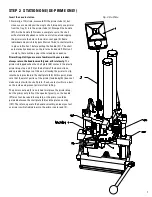
STEP 5:  STATION FOUR (WAD SEATING)

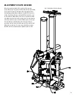
Insert a wad in the wad guide (106A) . Pull the operating handle 
(37) through a complete stroke . When the handle (37) is 
pulled, the spring (106B) around the wad guide rod (105) 
turns the wad guide bracket (101) to align the wad with 
the case . The unit then rises until the wad is stopped 
with the platen casting (107) by the wad ram (48) . 
The case continues upward until the spring fingers 
(77) have entered the case mouth, and then 
pushes the wad guide (101) upward until the wad 
is seated in the case . The spring fingers (77) 
have enough resistance to prevent the wad 
from going through until the spring fingers (77) 
are in the case . At the completion of the return 
stroke, the wad guide bracket (101) will swing 
forward for the next wad to be inserted . 

The 

wad guide bracket should have 1/8" clearance 
above the shells.

 The empty shells vary in length 

so a closer setting would not be beneficial . 

Be sure 

the wad seating ram (48) is set high enough for the 
wad to swing into position with out being folded by 
early contact with the wad seating ram (48). 
Wad pressure is adjusted by raising or lowering 
the wad seating ram (48).

 Most one-piece 

plastic wads today will self-adjust when the 
shell is crimped . 

Generally, the wad should 

be seated to allow 5/8" clearance between 
the case mouth and the shot.

Fig. 6: Wad Seating

Summary of Contents for Lock-N-Load 366 Auto

Page 1: ...Lock N Load 366 Auto Automatic Shotshell Reloader OPERATION MANUAL...

Page 2: ...tion 5 11 7 Crimp Starter Station 6 12 8 Crimp Station 7 13 9 Crimp Taper Station 8 14 Adjustment of Auto Advance 15 Trouble Shooting 16 Converting to Another Gauge 18 List of Illustrations Page 1 Fun...

Page 3: ...or powder manufactures is furnished when available to help you in getting started Unless you have experience in shot shell reloading ask your dealer to help you pick the best starting combination or c...

Page 4: ...t weight of powder and shot 3 While the charge bar is removed or pushed back check that the measure casting seals rubber washers are in the recess in the measure casting 4 Reinstall the bushings and p...

Page 5: ...reloader should begin by advancing a single shell through each station to familiarize himself with the operation and adjustment of each position The illustrated discussion which follows shows the 366...

Page 6: ...etween the size die ring cap 19 and the platen casting 107 When the handle 37 is returned the de prime punch guide 8 pushes the case from the die The expander 8 is threaded on the deprime bolt 62 whic...

Page 7: ...familiar with your reloader always return the handle smoothly and at first slowly The primer is dropped when the shell plate 45 contacts the plastic primer drop stop unit 78 at the bottom of the down...

Page 8: ...ate 45 back to station one and inspect the seated primer The primer should be flush with the case head If the primer is not fully seated the primer seater punch 20 must be adjusted Different brands of...

Page 9: ...ill advance to the Powder Drop station Normally we would leave the powder slide on but since we are taking one shell through each step push the powder slide back and shut off the powder Do this before...

Page 10: ...ce to prevent the wad from going through until the spring fingers 77 are in the case At the completion of the return stroke the wad guide bracket 101 will swing forward for the next wad to be inserted...

Page 11: ...shot drop tube 47 rise together to the top of the stroke In this fashion all the shot enters the case without being spilled No adjustment of this station is possible Upon completion of the stroke the...

Page 12: ...th damaged crimps follow these ridges A hole in the case mouth of should be left when the shell completes this station Hornady loaders come with eight point crimp starter installed but if you are usin...

Page 13: ...number of threads exposed above the large die body locking nut 15 as reference points for each brand of case For Winchester AA type shells ten to ten and one half threads should remain above the lock...

Page 14: ...e desired taper on the case mouth At this point in a normal reloading sequence you would have a completed shell at each station To begin reloading go back to the beginning and follow instructions for...

Page 15: ...ase casting 100 contacts the curve on the pivot arm 85 and the entire unit is cammed toward the left advancing the shells to the next position The cam bearing 12 is mounted off center on the bolt 25 s...

Page 16: ...heck the wad guide bracket 101 to see that the wad guide return spring 106B is attached and that the bracket is fastened to the wad guide rod 105 5 Check the charge bar cam 9 adjustment to see that it...

Page 17: ...s after being ejected from die Crimp not satisfactory in appearance Detach the rotating pawl shut off the powder and shot 1 If the crimp is concave sinks a Reduce the wad seating depth to see that the...

Page 18: ...is a fine progressive reloader once the first cycle is completed it kicks out a finished shell with every stroke ABOUT WADS AND WAD PRESSURE We recommend the use of 1 piece plastic wads They are more...

Page 19: ...9 444 453 426 402 423 408 447 480 456 414 426 372 378 477 468 435 402 318 318 432 348 360 468 432 318 318 429 363 363 20 456 465 435 414 429 417 456 489 468 423 438 381 384 483 447 327 330 441 357 369...

Page 20: ...20...

Page 21: ...t Description 46 1 390132 12 16 ga Powder Drop Tube 1 390144 20 Ga Powder Drop Tube 1 390156 410 28 Ga Powder Drop Tube 47 1 390133 12 16 ga Shot Drop Tube 1 390145 20 Ga Shot Drop Tube 1 390157 410 2...

Page 22: ...1 390120 E Clip 1 4 105 1 392035 Wad Guide Rod 106 1 390048 12 Ga Wad Guide Body 390050 20 Ga Wad Guide Body 390051 28 Ga Wad Guide Body 390052 410 Ga Wad Guide Body 106A 1 392041 12 ga Wad Guide Cap...

Page 23: ...ead shot only STEEL SHOT BUSHINGS For use in Models 155 266 only BUSHING ITEM 1 1 8 oz 8 1 2 190098 1 1 8 oz 7 1 2 190108 1 1 8 oz 8 190097 1 1 8 oz 9 190102 1 oz 7 1 2 190107 BUSHING ITEM 1 1 2 oz 19...

Page 24: ...18HMC0090 06 2018 T366 P O Box 1848 Grand Island NE 68802 1848 308 382 1390 800 338 3220 Fax 308 382 5761 www hornady com Hornady com contact_us...

Reviews: