Horizon Technology SPE-DEX 4790 Service Manual Download Page 14

13 


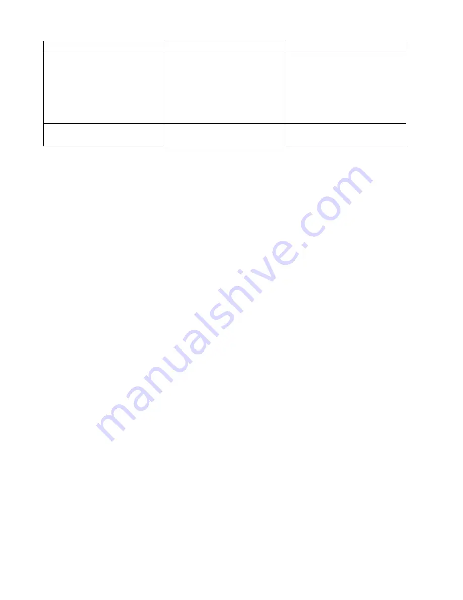
SYMPTOM 

PROBABLE CAUSE 

SOLUTION 

Waste valve is stuck open. 

With the extractor idle, fill a disk 

holder with water and verify that 

the fluid level does not decrease.  

If it does, examine the Waste 

vessels to determine which valve 

is stuck open and replace that 

valve. 

Keypad lights have dimmed or 

gone out. 

LEDs in Keypad are burned out. 

Replace Keypad. 


Summary of Contents for SPE-DEX 4790

Page 1: ...SPE DEX 4790 Solid Phase Extraction System Service Manual ...

Page 2: ...roduced or transmitted in any form or by any means electronic or mechanical including photocopying and recording or by any information storage or retrieval system except as may be expressly permitted in writing by Horizon Technology Inc SPE DEX is a trademark of Horizon Technology Inc All other product names herein are used for identification purposes only and are recognized as properties includin...

Page 3: ...acing the Bottle Holder O Ring 24 5 2 4 Replacing the Rinse Needle 24 5 2 5 Replacing the Collection Adapter Screws 25 5 2 6 Replacing the Modified Water Plug 25 5 2 7 Replacing the Module Feet 26 5 2 8 Replacing the Solvent and Water Waste Lines 26 5 3 Preventative Maintenance System 27 5 3 1 Check Valve Tool 27 5 3 2 Thermistor Height Adjustment Tool 27 5 3 3 Hydrophilic Solution 28 5 3 4 Water ...

Page 4: ...acing the IR Photointerruptor PN 16 0626 54 7 13 Replacing the SPE DEX 4790 Keypad PN 18 0588 CE 55 7 14 Replacing the Control Circuit Board PN 50 0145 CE 57 8 Schematics 58 8 1 Nitrogen and Solvent Delivery System 58 8 2 Waste and Vacuum System 59 8 3 Plumbing Schematics 60 8 3 1 MAC Valve and Water Inlet Valve Actuator 60 8 3 3 Prewet and Rinse Plumbing 61 8 3 4 Vacuum Plumbing 62 8 4 Electrical...

Page 5: ...ge To reduce the risk of electrical shock an Electro Static discharge mat should be used when troubleshooting or repairing the SPE DEX 4790 Personal Protective Equipment Due to the nature of use for the SPE DEX 4790 it is recommended that proper Personal Protective Equipment PPE be used when servicing it This should include safety glasses and gloves but may include additional PPE based on your saf...

Page 6: ...5 Notes ...

Page 7: ...4790 This controller may be either the stand alone 4700 Controller or a PC connected Envision Controller Both are capable of controlling up to eight Modules System A collection of up to eight 8 SPE DEX 4790 Modules connected to a single controller and waste system Preventative Maintenance PM A PM is preformed yearly and is designed to maintain a full System and through the measurement of various c...

Page 8: ...al elution solvent for best results Ensure that all gaskets are in place and in good condition Verify that all Plastic Coated Solvent Bottles are free from defects If needed replace them prior to pressurizing 2 2 Weekly Maintenance At the end of the week when the instrument is in routine operation Check the gas supply and tubing to ensure that all of the fittings are properly seated and that the t...

Page 9: ...rectly Verify that all nitrogen lines are free from kinks Verify that the bottle cap is tight and that both gaskets are present and undamaged Low No solvent in connected bottle Verify that enough solvent is contained within the solvent bottle to cover the bottom of the solvent filter Solvent Sip Tube not attached to cap Ensure that the sip tube is tightened into the cap Clogged Solvent Filter Cut ...

Page 10: ... Water into Disk Holder attached to a module Watch the waste containers and identify which one the water is pulled into Check Valve is stuck open Use the Check Valve Tool to cycle the Check Valve Place DI Water into a Disk Holder attached to a Module Replace Check Valve if necessary Extractor continually drains after first Prewet Incorrectly set Thermistor Use the Thermistor Height Tool to ensure ...

Page 11: ...ing used does not have defects on the threads or the rim Replace the Bottle Holder O Ring Replace the Cap Adapter Sample flows slowly or not at all Insufficient vacuum Verify that the vacuum source is set correctly Verify that the Water Waste Carboy Manifold is correctly seated Close the Water Waste Carboy Drain Insufficient prefilters used Use additional prefilters to increase the flow rate throu...

Page 12: ...confirm that there are scratches on the Spool Replace WIV Incorrectly set tension on WIV Look down into the WIV and run the Sample Drain method WIV should open in 1 second Opening faster indicates the tension may be insufficient Fluid leaking from Rinse Rod Rinse Valve is stuck open Increase the Solvent Bottle Pressure to 17 psi and run a method that fires only the affected valve If doing this doe...

Page 13: ...lace the IR sensor Fluid drips into the Collection Vessel Check Valve needs cleaning Use Check Valve Tool to free Check Valve Fill the Disk Holder with warm water and press and hold Abort then press Purge Check Valve needs to be replaced Replace Check Valve Low No Elution volume Unfamiliar method Confirm method steps Confirm that the method has been loaded onto the extractor in use Check Valve is ...

Page 14: ...tractor idle fill a disk holder with water and verify that the fluid level does not decrease If it does examine the Waste vessels to determine which valve is stuck open and replace that valve Keypad lights have dimmed or gone out LEDs in Keypad are burned out Replace Keypad ...

Page 15: ... Service Engineers will need to have one kit for each extractor Module The System Kit allows for the maintenance of the external components and accessories of the System only one kit is needed per waste container set If a user has a single controller but multiple waste containers an additional kit will be needed Some of the parts contained within the PM Kits are available by themselves if needed h...

Page 16: ...5 48 2605 Check Valve 48 2604 Thermistor set of two 30 0628 Bottle Holder O Ring 48 2608 Rinse Needle pack of two 02 0692 Thermistor Clip 50 0043 02 Solvent Waste Manifold 50 0051 02 Water Waste Manifold ...

Page 17: ...d Delivery Lines 120 4001 EX END Solvent Manifold End Block Includes 1 Solvent Manifold End Block 18 Manifold Plugs 18 Solvent Manifold Delivery Lines 9 Manifold to Manifold Delivery Lines 50 0173 04 Solvent Manifold Delivery Lines 50 0103 01 Solvent Bottle Delivery Lines includes eight solvent lines and one nitrogen line 50 0172 01 Solvent Bottle Tops pack of eight ...

Page 18: ...8 2772 Solvent Stone includes ferrule 50 2770 Manifold to Manifold Delivery Line single line only nine needed for complete set 02 0029 01 Solvent Manifold End Block 02 0028 01 Solvent Manifold Through Block ...

Page 19: ...te collection system or controller o Check Valve Tool o Thermistor Height Adjustment Tool o Hydrophilic Solution o Water Waste Manifold o Vacuum Line Kit 48 4502 SPE DEX 4790 Module PM Kit This kit is designed to service a single SPE DEX 4790 module For systems containing multiple modules the same number of kits will be ordered ...

Page 20: ...o Check Valve o Check Valve Screws 3 Included o Thermistors set of two o Bottle Holder O Ring o Solvent and Water Waste Lines o Rinse Needle o Collection Adapter Screws three Included o Modified Water Plug ...

Page 21: ...20 o Module Feet six included 50 2769 Vacuum Gauge Kit This tool allows for the measurement and analysis of the condition of the subsystems for a SPE DEX 4790 ...

Page 22: ...n Testing 2 Turn on the computer which is used to run the System 3 Turn the Envision s power on 4 Turn on the Nitrogen Source and regulate it to between 60 and 80 psi 4 1 to 5 5 bar 5 Turn on the Vacuum Source and regulate it to between 23 and 26 Hg 779 to 880 mbar 6 Record the vacuum and nitrogen readings in the table 7 Using the computer connect to the Envision and ensure that all Modules connec...

Page 23: ...pressurize the Solvent Bottles This will prevent solvent from moving during the next tests b Fill a beaker or other cup partially with tap water c Slide the Thermistor Clip with the Thermistors attached off of the Downtube as shown in the picture d Create a method within the Envision system as follows Step Soak Time Dry Time Prewet 1 0 sec 60 sec Sample Process Air Dry 60 sec Rinse 1 0 sec 60 sec ...

Page 24: ...located for the elution process to function Note The Collection Adapter is made of soft plastic and can have the screw holes stripped if the screws are tightened too forcefully Care should be taken 5 2 2 Replacing the Thermistors 1 Remove the five 5 screws on the back of the Module using a 1 4 nut driver or screwdriver 2 Remove the Module cover by holding the bottom of each side and pushing the bo...

Page 25: ... with the Cap Adapter If this gasket is worn too far then air leaks may develop and sample overflows will occur 1 Using a pick or other similar tool hook the O Ring contained within the Bottle Holder and pull the O Ring out 2 Replace the O Ring with the new one by hand Note The Bottle Holder is made of soft plastic and can be scored easily if care is not taken in the removal process It is recommen...

Page 26: ... in it so that the vacuum contained within the Water Waste lines are relieved after a run Doing this removes the load from the valves and prolongs their lifetime With time this hole can become occluded and the flow rate of a sample will increase and may lead to poor results 1 Remove the five 5 screws on the back of the Module using a nut driver or screwdriver 2 Remove the Module cover by holding t...

Page 27: ...ave solid material which builds up over time The replacement of these lines yearly will maintain the proper flow rate of fluid through them 1 On the rear of the instrument remove and discard the Waste Waste and the Solvent Waste lines 2 Install the new Solvent Waste line the one with the black collar on it onto the Solvent Waste port 3 Install the new Water Waste line the one with no collar on it ...

Page 28: ...Tool should bounce freely up and down with no resistance Note The Check Valve contains a small ceramic ball which may be damaged if a substitute is made for the Check Valve Tool Materials which are harder than the ceramic may chip or gouge the ball 5 3 2 Thermistor Height Adjustment Tool The height of the Thermistors determines the amount of solvent which is dispensed during a Prewet step as well ...

Page 29: ... the valve by turning the shaft that protrudes from the rear of it using a wrench 6 Pour the Hydrophilic Solution into the Bottle Holder until it comes up to just below the Bottle Holder Gasket 7 Open and Close the Water Inlet Valve manually two or three times 8 Let the Module soak for at least two hours overnight is best 9 Drain the Hydrophilic Solution back into the bottle it came in to be used ...

Page 30: ...ing from the top of the Water Waste Manifold 2 Remove the Vacuum Line from the rear of the Solvent Waste Manifold 3 Remove the Vacuum Line from the Vacuum Pump 4 Discard all Lines and the T Fitting 5 Attach the new T Fitting to the top of the Water Waste Manifold 6 Attach one end of the larger diameter Vacuum Line to the Vacuum Pump 7 Attach the other end to one port of the T Fitting 8 Attach one ...

Page 31: ...at the end user already has connected to the units Step Soak Time Dry Time Prewet 1 0 sec 30 sec Prewet 2 0 sec 30 sec Prewet 3 0 sec 30 sec Prewet 4 0 sec 30 sec Prewet 5 0 sec 30 sec Sample Process Air Dry 60 sec Rinse 1 0 sec 30 sec Rinse 2 0 sec 30 sec Rinse 3 0 sec 30 sec 8 Load the method to all Modules 9 Prepare all Modules by loading an empty Disk Holder a Sample Container with 250 500 mL ...

Page 32: ... onto all Modules f With the Vacuum Test gauge installed into the Module Platform press Start g Using the beaker or cup of water after 15 seconds put the Thermistors into the water This will trick the SPE DEX into moving from dispensing solvent to draining the solvent activating the Solvent Waste valve h Measure and record the Solvent Waste vacuum The nominal value for this reading is the value th...

Page 33: ...rchased from Horizon Technology Part Description 50 2457 Bottle Holder includes Bottle Holder O Ring and Rinse Needle 48 2607 Water Inlet Valve 48 2606 Downtube Assembly 50 2498 Sample Collect Valve 50 2535 Solvent Waste Valve or Sample Waste Valve 50 2536 Prewet and Rinse Valve 24 V ...

Page 34: ...er Inlet Valve Actuator 02 0602 Collection Adapter 50 2237 MAC Valve includes connectors and barbs 50 0629 Exhaust Fan includes Molex connectors 50 2233 Spring Motor includes bolt and nut 16 0626 IR Photointerrupter ...

Page 35: ...34 18 0588 CE SPE DEX 4790 Key Pad 50 0145 CE Control Circuit Board 50 0027 03 External Nitrogen Regulator ...

Page 36: ...0 Module TOOLS None PARTS REQUIRED 50 2457 Bottle Holder CAUTIONS Prior to beginning the Module being worked on should have all rinse solvents drained and the lines flushed to prevent spills Prior to beginning the Controller should be turned off and the Module should have the data power cable unplugged PROCEDURE 1 Pull up on the Bottle Holder to detach it from the Water Inlet Valve 2 Unscrew the 3...

Page 37: ...d PROCEDURE 1 Pull up on the Bottle Holder to detach it from the Water Inlet Valve Do not remove the Rinse lines from the Bottle Holder 2 Remove the 4 Hex screws that hold the Water Inlet Valve and the Downtube Assembly onto the Module 3 Locate and unscrew the two phillips head screws on the bottom of the Downtube Assembly Note Care should be taken not to kink the Prewet lines that are attached to...

Page 38: ...alve Do not remove the Rinse lines from the Bottle Holder 2 Remove the 4 Hex screws that hold the Water Inlet Valve and the Downtube Assembly onto the Module 3 Locate and unscrew the two phillips head screws on the bottom of the Downtube Assembly Set the Water Inlet Valve aside for reuse Note Care should be taken not to kink the Prewet lines that are attached to the Downtube Assembly when unscrewi...

Page 39: ...38 ...

Page 40: ...using the inch Nut Driver 2 Remove the cover by holding the bottom of each side and pushing the bottom backwards to disengage the front locking tabs Lift the cover off 3 Locate the mounting bracket The Sample Collect Valve is located on the rear side of the mounting bracket 4 Loosen the 5 16 hexagonal nut and the screw circled in red 5 Depress the locking mechanism and separate the two halves of t...

Page 41: ...x connector taking care to orient the pin such that the u channel aligns with the post inside the Molex connector The pin will only fit in one direction 15 Attach both halves of the Molex connector together 16 Replace the bracket screw but do not fully tighten Tighten the 5 16 hexagonal nut while holding the bracket to ensure that the bracket is in place Tighten the bracket screw 17 Place the extr...

Page 42: ...d the Module should have the data power cable unplugged PROCEDURE 19 Remove the five 5 screws from the rear of the Module using the inch Nut Driver 20 Remove the cover by holding the bottom of each side and pushing the bottom backwards to disengage the front locking tabs Lift the cover off 21 Locate the mounting bracket and identify the valve which needs to be replaced using the labeled picture 22...

Page 43: ... Using the removed screws attach the replacement valve to the valve bracket 32 Plug the electrical pins into the Molex connector taking care to orient the pin such that the u channel aligns with the post inside the Molex connector The pin will only fit in one direction 33 Attach both halves of the Molex connector together 34 Replace the bracket screw but do not fully tighten Tighten the 5 16 hexag...

Page 44: ... the solvent lines purged of solvents to prevent spills PROCEDURE 1 Remove the five 5 screws from the rear of the Module using the inch Nut Driver 2 Remove the cover by holding the bottom of each side and pushing the bottom backwards to disengage the front locking tabs Lift the cover off 3 Locate the valve which needs to be replaced on the manifold 4 Disconnect the Molex connector 5 Carefully clip...

Page 45: ...atter 10 Tighten the valve collar by turning it clockwise 11 If removed reinstall the valve block into the SPE DEX 4790 12 Plug the electrical pins into the Molex connector taking care to orient the pin such that the u channel aligns with the post inside the Molex connector The pin will only fit in one direction 13 Attach both halves of the Molex connector together 14 It is recommended that prior ...

Page 46: ...he bottom of each side and pushing the bottom backwards to disengage the front locking tabs Lift the cover off 3 Remove the 4 screws holding the Actuator to the Front Panel 4 Loosen the set screw on the Actuator Key and remove from the Actuator 5 Install the Actuator Key onto the new Actuator 6 Twist the Actuator Key so that the flat side of the Actuator Shaft is positioned upwards 7 Install the n...

Page 47: ...46 ...

Page 48: ...nd set the Check Valve aside if it is going to be used again 2 Press down on the front platform on the SPE DEX 4790 and using a Phillips screwdriver unscrew the Collection Adapter from the platform 3 Cut through one of the two vacuum lines attached to the Collection Adapter 4 Remove the remaining tubing on the barb fitting so the barb may be reused 5 Using a Wrench unscrew both barb fittings from ...

Page 49: ... be turned off and the Module should have the data power cable unplugged The nitrogen supply should be turned off and the lines vented to atmosphere PROCEDURE 9 Remove the five 5 screws from the rear of the Module using the inch Nut Driver 10 Remove the cover by holding the bottom of each side and pushing the bottom backwards to disengage the front locking tabs Lift the cover off 11 Locate the MAC...

Page 50: ...e line going into port B on the MAC Valve should come from the bottom fitting on the Water Inlet Valve Actuator c The bottom line extends to the gas supply port on the bulkhead of the SPE DEX 4790 17 With the tubing attached replace the screws which hold the MAC Valve in place 18 Plug the electrical pins into the Molex connector taking care to orient the pin such that the u channel aligns with the...

Page 51: ...e controller and power on the unit 22 Within the Envision Controller load and run the Sample Drain method Observe the Water Inlet Valve Actuator Shaft directly in the middle of the Actuator and confirm that the shaft rotates 90 degrees in one second If necessary adjust the IN screw in quarter turn increments to increase the speed that the valve opens 23 Place the extractor cover on to the extracto...

Page 52: ...e Module using the inch Nut Driver 2 Remove the cover by holding the bottom of each side and pushing the bottom backwards to disengage the front locking tabs Lift the cover off 3 Locate the Exhaust Fan and following the power wires unplug the Fan from the Control Circuit Board 4 Remove the four nuts that hold the Exhaust Fan to the Chassis using the Wrench 5 Install the new Exhaust Fan making sure...

Page 53: ...ssware attached as a Collection Vessel should be removed PROCEDURE 1 Remove the five 5 screws from the rear of the Module using the inch Nut Driver 2 Remove the cover by holding the bottom of each side and pushing the bottom backwards to disengage the front locking tabs Lift the cover off 3 Remove the screw from the rear of the Platform mount as seen in the above picture Care should be taken with ...

Page 54: ... in red 6 Swing the valve mounting bracket out of the way and using a screwdriver remove the four screws from the Spring Motor 7 Install the new Spring Motor 8 Pull the Spring Motor Wire over the Pivot Wheel and attach to the Platform 9 Reinstall the mounting bracket and replace the cover ...

Page 55: ...e data power cable unplugged PROCEDURE 1 Remove the five 5 screws from the rear of the Module using the inch Nut Driver 2 Remove the cover by holding the bottom of each side and pushing the bottom backwards to disengage the front locking tabs Lift the cover off 3 Locate the Photointerruptor and remove the two nuts using the inch Nut Driver 4 Unplug the old Photointerruptor and install the new Phot...

Page 56: ...wer cable unplugged PROCEDURE 1 Remove the five 5 screws from the rear of the Module using the inch Nut Driver 2 Remove the cover by holding the bottom of each side and pushing the bottom backwards to disengage the front locking tabs Lift the cover off 3 Unplug the Keypad from the Control Circuit Board 4 Using a screwdriver remove the two screws on the front end of the Control Circuit Board loosen...

Page 57: ...the chassis 7 Insert and run the Keypad Ribbon through the chassis and route it behind the Control Circuit board 8 Tighten or replace all screws to the Control Circuit Board making sure to attach the KeyPad s Grounding Wire to the bottom front screw 9 Replace the cover ...

Page 58: ...ttom backwards to disengage the front locking tabs Lift the cover off 3 Unplug the Keypad Ribbon cable both Thermistors the IR Sensor and the Exhaust Fan from the Control Circuit Board 4 Using a screwdriver remove the four 4 screws holding the Control Circuit Board 5 Replace the Control Circuit Board with the new part and tighten all screws making sure to attach the KeyPad s Grounding Wire to the ...

Page 59: ...58 8 Schematics 8 1 Nitrogen and Solvent Delivery System ...

Page 60: ...59 8 2 Waste and Vacuum System ...

Page 61: ...ics 8 3 1 MAC Valve and Water Inlet Valve Actuator Water Inlet Valve Status MAC Valve Line A MAC Valve Line B Closed Not Pressurized Pressurized Open Pressurized Not Pressurized Supply A B MAC Valve Water Inlet Valve Actuator ...

Page 62: ...61 8 3 3 Prewet and Rinse Plumbing PW 1 PW 2 PW 3 PW 4 PW 5 R 1 R 2 R 3 Valve Manifold Water Inlet Valve Assembly Supply ...

Page 63: ...62 8 3 4 Vacuum Plumbing Solvent Waste Valve Water Waste Valve Elution Valve Modified Luer Plug Collection Adapter To Waste ...

Page 64: ...Prewet 5 Grey 8 6 Water Waste White 9 15 Rinse 3 Black 10 6 J 12 Prewet 3 Rinse 1 Brown 11 1 Prewet 1 Red 12 8 J 14 Prewet 4 Rinse 2 Orange 13 3 Solvent Waste Yellow 14 4 Solvent Waste Green 15 7 Prewet 4 Blue 16 2 J 16 Prewet 1 Rinse 3 Violet 17 13 Rinse 2 Grey 18 4 Prewet 2 White 19 Not Used Black 20 10 Prewet 5 Brown 21 5 Water Waste Red 22 1 Solvent Collect Orange 23 5 Prewet 3 Yellow 24 7 MAC...

Page 65: ...64 Conn A Conn B Conn C Conn D 2 1 4 3 6 5 8 7 10 9 12 11 14 13 16 15 18 17 20 19 22 21 24 23 26 25 Conn A Conn B Conn C Conn D ...

Page 66: ...a signal is being given for a valve to fire The LEDs are highlighted in red below LED 1 Rinse 4 LED 9 Not Used LED 2 Sample Collect LED 10 Prewet 2 LED 3 Rinse 3 LED 11 Prewet 5 LED 4 Solvent Waste LED 12 Prewet 1 LED 5 Rinse 2 LED 13 Prewet 4 LED 6 Water Waste LED 14 Not Used LED 7 Rinse 1 LED 15 Prewet 3 LED 8 Water Inlet Valve LED 16 Prewet 6 ...

Page 67: ...e Closes Any More Prewets Are Prewets Programmed Timer 0 seconds Solvent Waste Valve Opens Solvent Waste Valve Closes Top Thermistor Cool OR Timer 60 s Specified Prewet Valve Closes Timer 60 s Top Thermistor Cool Solvent Waste Valve Opens Solvent Waste Valve Closes Soak Dry Solvent Waste Valve Opens Programmed Time Programmed Time Wait 1 s Sample Process Sample Process ...

Page 68: ...hermistor Cool OR Timer 45 s Timer 45 s Top Thermistor Not Cool Timer 45 s Top Thermistor Cool Bottom Thermistor Warm Timer 0 s Bottom Thermistor Cool Timer 45 s Bottom Thermistor Warm AND Timer 45 s Water Waste Valve Opens Water Waste Valve Closes Wash Wash Sample Process ...

Page 69: ...d Timer 0 seconds Solvent Waste Valve Opens IR Sensor Not Covered Solvent Waste Valve Closes Soak Dry Solvent Waste Valve Opens Programmed Time Programmed Time Air Dry Air Dry Covered Not Covered Specified Rinse Valve Opens Specified Rinse Valve Opens Specified Rinse Valve Closes Wait 8 s Wait 1 s ...

Page 70: ...69 8 5 4 Air Dry Cycle Air Dry Water Waste Valve Closes Programmed Time Rinse Water Waste Valve Opens Solvent Waste Valve Closes Wait 15 s Solvent Waste Valve Opens ...

Page 71: ...Wait 15 s Are Rinses Programmed Timer 0 seconds IR Sensor Not Covered Soak Elute Sample Collect Valve Opens Programmed Time Programmed Time Wait 10 s Stand By Stand By Covered Not Covered Specified Rinse Valve Opens Specified Rinse Valve Opens Specified Rinse Valve Closes Wait 8 s ...

Page 72: ...following documents are kept separately and can be furnished upon request o PM Service Parts Part Replacement and Recommended Inventory o Pre Installation Requirements o Instrument Qualification Operational Qualification o Instrument Maintenance Form ...

Reviews: