172
8-3
Four Stitching Kit FST-200
8-3-4 Wire Attachment (continued)
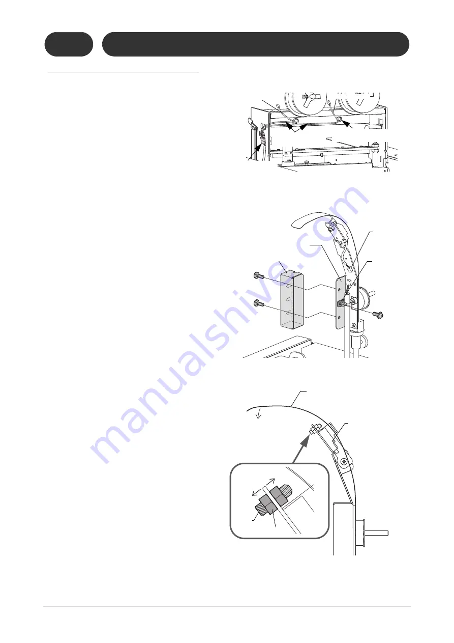
6. Install the relay wire for the sensor.
- Connect the relay wire to the connector (8
pins) on the rear side of the stitcher head
unit.
- Lock the relay wire by using nylon ties
together with other cables.
7. Lock the wire saddle of the relay wire to the
sensor bracket.
8. Connect the cable from the sensor.
9. Install the cable cover.
- Place the excess cable inside of the cable
cover.
4
Adjust the detecting range of for
the sensor.
1. Loosen the lock nut and turn the screw
toward the direction A.
- Check that the sensor is not On when the
wire guide is pushed down and touches the
screw head.
2. Pull the screw to the direction B.
- Pull the screw until the sensor just turns on
when the wire guide is pushed down.
3. Additionally pull the screw with 1/2-turn.
4. Tighten the lock nut.
5
Thread the wire to the stitcher
head.
- Refer to 6-2.
11119
70301D1
11119
80304E1
Connect the relay
wire with the 8-
pins connector.
Lock together with
other cables.
Pass through this hole
to the opposite side.
Cable No. 137
Cable No. 136
Cable Cover
Sensor Bracket
Cable for
Sensor
Wire Saddle
11119
80304F1
11119
80304G1
A
B
Wire Guide
Screw
Lock Nut
ON = The lamp lights.
OFF = The lamp lights
out.
Summary of Contents for Bookletmaker FC-200A
Page 84: ...This page is intentionally left blank...
Page 94: ...This page is intentionally left blank...
Page 146: ...This page is intentionally left blank...
Page 202: ...This page is intentionally left blank...
Page 217: ...This page is intentionally left blank...
Page 218: ...Manufacturer Phone 81 75 934 6700 Fax 81 75 934 6708 www horizon co jp...


