Installation
22
Note
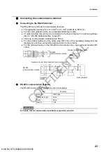
The max. load resistance of transmission output is 900
.
Negative terminal for transmission output OUT1 (
) and OUT2 (
) are internally connected and
have the same electric potential.
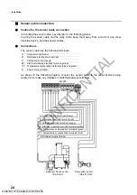
Contact input terminals and flow switch input terminals
The applicable electric wire is 0.14 mm
2
to 2.5 mm
2
(AWG 26 to AWG 14).
For the contact input and the flow switch input, use a twisted shielded pair cable.
If lightning might strike, install an arrester on the output side of the HR-200 and on the
side of receiving instruments.
To terminate the cable, strip the covering at the end by 11 mm, and then connect the
stripped end to the terminal.
Note
Contact resistance should be less than 100
.
For the flow switch input, use a dedicated shielded cable.
Tip
When the contact input terminals are short-circuited, the EXT1 indicator on the display part lights
up.
The flow switch will be closed while water is flowing, opened when flow rate is coming down to
the low limit. The EXT2 will light up when the contact is closed.
FS
(flow switch input)
(+)
EXT.IN
(contact input)
(
)
(+)(
)
h19136 | UTC 2020/03/30 3:34:51
CONFIDENTIAL


