


SYSTEM DESCRIPTION, INSTALLATION, AND MAINTENANCE MANUAL
MCS--4200/7200 Multi--Channel SATCOM System
23--20--35
15 Jul 2006
Honeywell International Inc. Do not copy without express permission of Honeywell.
Page 6--50
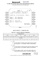
Figure 6-8 (Sheet 5).
Configuration Data
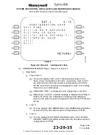
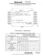
(g) CONFIGURATION DATA Page 6 (Figure 6-8, sheet 6):
1
Data Fields
a
Lines 4 thru 9
(1) These lines display X(0)* or X(1)* left-justified as shown in the
figure, where X represents E, F, G, H, J, and K, respectively. X(0)*
or X(1)* is determined by the states of system configuration pins
TP11E, TP11F, TP11G, TP11H, TP11J, and TP11K. Asterisks are
displayed in column 5 to indicate these pins are a coded group.
(2) Beginning in column 6, textual messages are displayed (refer to
Table 6-11) in lines 4 thru 9 (as needed), where an x indicates the
message(s) to be displayed based on the state of system
configuration pins TP11E, TP11F, TP11G, TP11H, TP11J, and
TP11K.


