22
SWIFT® Smart Wireless Integrated Fire Technology Manual —
P/N LS10036-000SK-E:G 4/13/2020
WSK-WGI Wireless System Gateway
Operations
3.
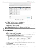
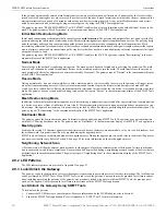
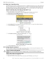
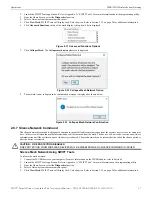
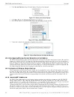
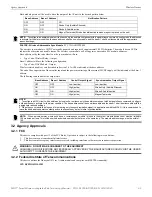
A Hall Sensor Activation window displays. On hall sensor activation, the LED on the gateway blinks yellow.
4.
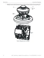
Place a magnet on either of the gateway sensors within 120 seconds.
5.
The LED blinks normal upon hall sensor activation. The gateway is unlocked and a confirmatory message is displayed.
Password Reset
To reset the password, contact technical support.
2.9.4 Enable/Disable Max Gateway Trouble Reporting
This feature is used to determine if the permitted number of Honeywell SWIFT systems that can co-exist in range of each other without
reducing overall performance has been exceeded. The default setting is On (enabled).
Completed Wireless Network
Turning off the MAX GATEWAY trouble reporting in this case prevents subsequent installation attempts from causing a trouble on a
properly installed and commissioned system. When the wireless installation is completed and there are no possibilities of overlapping
systems, turn off MAX GATEWAY trouble reporting when all three of the following conditions are true:
1.
The entire fire system installation has been completed.
2.
There is no MAX GATEWAY trouble indication present in the completed system.
3.
The system has been inspected, tested, and approved by the authority having jurisdiction.
Possible Wireless Mesh Overlap
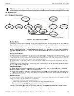
Generally, only four SWIFT wireless mesh gateways, along with their associated devices, are permitted to be installed within an overlap-
ping wireless region. The MAX GATEWAY trouble is generated when a fifth gateway mesh is detected and the maximum limit is
exceeded. When there is a MAX GATEWAY trouble present in the system, it is permitted to turn off MAX GATEWAY trouble reporting
after completing the following evaluation method with successful results. For the result to be successful, the signal strength between
devices in any one mesh must be at least 20 dB stronger than the signals seen from another mesh. If the 20 dB requirement is not met, or
if the evaluation cannot be performed due to access restrictions, the number of overlapping mesh systems must be reduced to four to
ensure the wireless system performs according to UL requirements. This could mean that additional mesh systems cannot be installed in
the area.
Evaluation Process
1.
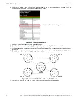
Locate all the SWIFT wireless mesh systems in the area. Access to all mesh gateways in the area and to the closest edge devices
between overlapping meshes is required and the SLC addresses of the edge devices must be known. The edge devices that must be
accessible are located at the ends of the dotted lines represented in Figures 2.21 and Figure 2.24. If location of devices or access to
them is not possible, the addition of a fifth wireless mesh is not permitted in this area.
2.
Identify the devices on the edge of each mesh.
3.
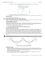
Find the closest edge device from each mesh to the closest edge of the new mesh. Except as noted in Figure 2.25, four pairs of
devices should be identified given there are five overlapping meshes in the area.
ha
ll se
nso
r.
pn
g
NOTE:
Signal strength is represented using negative numbers. So, 30 is 20 dB stronger than 50. Refer for Figure 2.23 for an example.
mesh
#1
mesh
#2
mesh
#4
mesh
#3
mesh
#5
-2
0 d
B
-2
0 d
B
-20
dB
-20
dB
Figure 2.20 Basic Overlapping Mesh Example

