Honeywell nfs2-3030 Programming Manual Download Page 35

NFS2-3030 Programming Manual —

 P/N 52545:K1 03/20/2012  

35

Panel Program

Program

• Prioritized Audio Matrix (PAM) speaker points, in the format NxxxIyyyyAzzSn.  xxx = the 

DVC node number, yyyy = the input number in the PAM, zz = the DAA address on the 
Digital Audio Loop (01 through 32), and n = the DAA speaker circuit (1 through 4).

Soft Keys

All soft keys function like they do on the ACS Point Programming Screen.

3.2.9  Supervision

From the Panel Program Menu (1), select 

SUPERVISION

 to display the following screen.

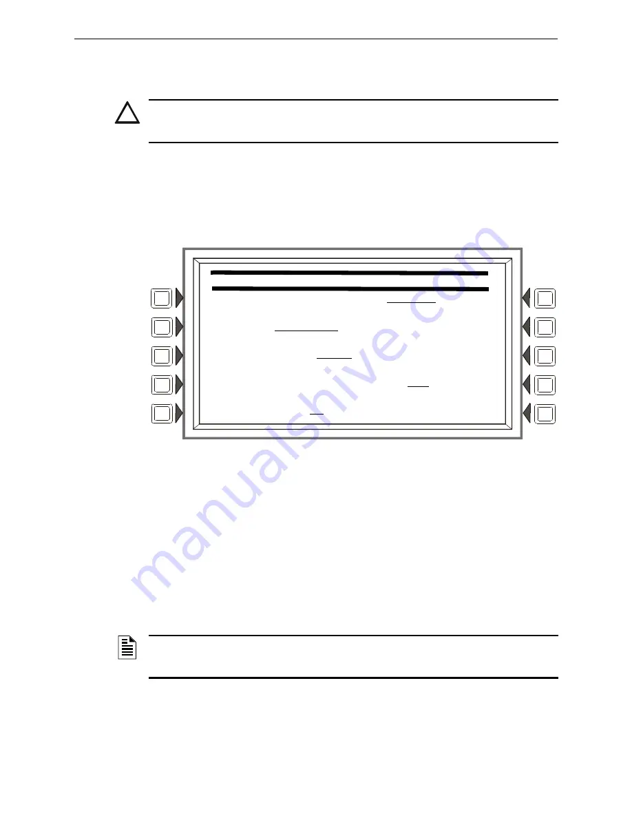
Figure 3.20  Supervision Screen

Soft Keys

MAIN


POWER


SUPPLY


AC


FAIL


ADDRESS

: Press to enter the “Monitor AC Fail” (base plus one) 

address of the main power supply. Refer to the main power supply manual for complete addressing 
information. Enter the power supply address and press 

ACCEPT

.

The LCD backlight will turn off when this power supply experiences AC failure (see 

BACKLIGHT


in Section 3.2.7, “LCD Programming”, on page 28).

PRINTER:

 Press to scroll through the types of printer supervision: 

NONE

40-COLUMN

,


40-COLUMN


SUPERVISED

80-COLUMN

80-COLUMN


SUPERVISED

40


GRAPHIC,


80


GRAPHIC,


80


GRAPHIC


SUPERVISED

. The printer will not be active if 

NONE

 is selected. If a 

SUPERVISED

 selection is made, the printer will be supervised. Default: 

NONE 

!

CAUTION:

DO NOT MIX GENERAL ZONES WITH OTHER SOURCE TYPES FOR AN ACS 

CONTROL POINT. PROGRAM UP TO EIGHT GENERAL ZONES 

OR

 UP TO EIGHT OTHER 

CONTROL POINT TYPES.


                              S U P E R V I S I O N                            


M A I N   P S   A C   F A I L   A D D R E S S :   L X X M X X X                


P R I N T E R :   8 0 - C O L U M N                                            


C R T   B A U D   R A T E :   5 7 6 0 0                               M O R E


A U X I L I A R Y   T R O U B L E   R E P O R T I N G : N O         A C C E P T


T A M P E R   I N P U T :   N O                                         B A C K

NOTE:

When changing from an 80-column or 80-column supervised to an 80 graphic or 80 

graphic supervised printer (or vice-versa), settings must be changed at the printer. Refer to this 
panel’s installation manual for the settings.

Summary of Contents for nfs2-3030

Page 1: ...K1 P N 52545 K1 ECN 12 0424 Document 52545 03 20 2012 Rev Fire Alarm Control Panel NFS2 3030 Programming Manual ...

Page 2: ... fire Smoke detectors cannot be expected to provide adequate warning of fires caused by arson children playing with matches especially in bedrooms smoking in bed and violent explosions caused by escaping gas improper storage of flammable materials etc Heat detectors do not sense particles of combustion and alarm only when heat on their sensors increases at a predeter mined rate or reaches a predet...

Page 3: ...ards Failure to do so can damage circuits Remove all electronic assemblies prior to any drilling filing reaming or punching of the enclosure When possible make all cable entries from the sides or rear Before making modifi cations verify that they will not interfere with battery trans former or printed circuit board location Do not tighten screw terminals more than 9 in lbs Over tightening may dama...

Page 4: ...opriate version for a specific application Documentation Feedback Your feedback helps us keep our documentation up to date and accurate If you have any comments or suggestions about our online Help or printed manuals you can email us Please include the following information Product name and version number if applicable Printed manual or online Help Topic Title for online Help Page number for print...

Page 5: ... 3 1 General Information 17 3 2 Panel Program 18 3 2 1 Panel Program Menu 1 18 3 2 2 Network Parameters 18 3 2 3 Network Mapping 20 3 2 4 Panel Settings 21 3 2 5 Panel Timers Menu 1 26 3 2 6 Panel Timers Menu 2 28 3 2 7 LCD Programming 28 3 2 8 ACS Programming 29 3 2 9 Supervision 35 3 3 Panel Program Menu 2 37 3 3 1 Password Change 37 3 3 2 Weekly Occupancy Schedule 37 3 3 3 Remote Display Menu 3...

Page 6: ...lication Corrupt Screen 90 Appendix A Menu Hierarchy 91 A 1 Screens Overview 91 Appendix B Releasing Applications 96 B 1 Releasing Zones 96 B 2 NFPA Releasing Applications 97 B 3 Abort Switches 97 B 3 1 ULI Abort Switch 99 B 3 2 IRI Abort Switch 100 B 3 3 NYC Abort Switch 101 B 3 4 AHJ Abort Switch 103 B 3 5 Cross Zones 104 B 3 6 Using Type Codes for Releasing Zones 105 B 4 Miscellaneous 116 B 4 1...

Page 7: ... and Equations 131 E 1 Zones 131 E 2 Equations 132 E 2 1 Arguments 133 E 2 2 Logic Equations 133 E 2 3 Trouble Equations 136 Appendix F Detector Initialization 137 F 1 Overview 137 F 2 To Replace a Detector with a Different Type of Detector 137 Appendix G Type Codes 138 G 1 What Are Type Codes 138 G 2 How to Select a Type Code 138 G 3 Type Codes for Input Devices 138 G 3 1 Overview 138 G 3 2 Type ...

Page 8: ...or options listed below must be approved by the local AHJ WARNING INFORMATION ABOUT PROCEDURES THAT COULD CAUSE IRREVERSIBLE DAMAGE TO THE CONTROL PANEL IRREVERSIBLE LOSS OF PROGRAMMING DATA OR PERSONAL INJURY CAUTION INFORMATION ABOUT PROCEDURES THAT COULD CAUSE PROGRAMMING ERRORS RUNTIME ERRORS OR EQUIPMENT DAMAGE NOTE Information that highlights an important part of the preceding or subsequent ...

Page 9: ...mpatibility Document 15378 Fire Alarm Control Panel FACP and Main Power Supply Installation Document Number NFS2 3030 Installation Operations and Programming Manuals 52544 52545 52546 AMPS 24 E Addressable Power Supply Manual 51907 SLC Wiring Manual 51253 Note For individual SLC Devices refer to the SLC Wiring Manual Note Also documents some retrofit equipment manufactured under UL 8th edition Aud...

Page 10: ... Manual Smoke and HVAC Control Station Manual 15712 RPT 485W RPT 485WF EIA 485 Annunciator Loop Repeater 15640 DPI 232 Manual 51499 TM 4 Installation Document Reverse Polarity Transmitter 51490 UDACT Manual Universal Digital Alarm Communicator Transmitter 50050 UDACT 2 Manual Universal Digital Alarm Communicator Transmitter 54089 ACT 1 Installation Document 52527 ACT 2 Installation Document 51118 ...

Page 11: ...rol Refer to the Canadian Applications appendix in this panel s installation manual 1 4 1 Features Programming features include the following Ease of use Field program the control panel without special software skills Local programming program directly from the control panel keypad to reduce installation time PC programming input long data entry programming information on a PC transfer programming...

Page 12: ...manual before programming Enter change master and user passwords Enter panel and network parameters Program all devices and thoroughly test the entire system The Walk Test feature can be used to test devices and their programming Make a hard copy record of the program on the printer Save the program by uploading it using VeriFire Tools 1 7 Getting Started Once the system has been physically instal...

Page 13: ...to display the following screen Enter a new password that will replace the factory default password there can be up to eight alphanumeric characters Press the enter key on the keyboard RE ENTER PASSWORD will appear Reenter the password for verification Press enter to save the new password Figure 1 2 Change Master Password Screen CHANGE PASSWORD MASTER PASSWORD USER PASSWORD BACK NOTE Only a master...

Page 14: ... the enter key on the display keyboard to enter the information ENTER PASSWORD Press to enter a new password Enter up to eight alphanumeric characters then press enter RE ENTER PASSWORD will appear Retype the password for verification ACCEPT After entering all password information and retyping the password at the prompt press this soft key to save all the password information Incorrect or Forgotte...

Page 15: ...cknowledged events Refer to this panel s operations manual for an illustration and description of the Event Counts Display 2 2 Multiple Event List Pressing the Multiple Event List soft key shows off normal events simultaneously in groups of eight It displays automatically for off normal events when the Canada event order has been selected Refer to Event Ordering in Panel Settings on page 21 for in...

Page 16: ...er Status soft key brings up screens for panel programming point programming autoprogramming clear programming altering the status of points walk test and other information Refer to Sections 3 and 4 for a full description of Program Alter Status 2 6 Printer Functions Pressing the Printer Functions soft key brings up screens to print reports Refer to this panel s operations manual for a description...

Page 17: ...ng screen will display Figure 3 1 Program Alter Status Screen Press a soft key with the word program in its menu to bring up the associated program menu When programming the panel for the first time press the DELETE PROGRAM MENU soft key which brings up the Delete Program Menu screen Refer to Figure 3 55 Press the CLEAR ALL PROGRAMMING button then ACCEPT to ensure that the panel is set to defaults...

Page 18: ... choices Figure 3 2 Panel Program Menu 1 Screen 3 2 2 Network Parameters Press the Network Parameters soft key on Panel Program Menu 1 to bring up the following screen If the panel will operate as a standalone unit and not part of a network the node label is the only field that needs to be entered it is the label that appears as part of the System Normal message Figure 3 3 Network Programming Scre...

Page 19: ...fault HIGH IP ACCESS Press this soft key to bring up the IP ACCESS screen ACCEPT Press this soft key to save the information entered on this screen IP ACCESS Screen This screen allows the programmer to set the IP Access This setting allows the disabling enabling of commands downloads and programming from the Wide Area Network WAN Figure 3 4 IP Access Screen Soft Keys IP ACCESS Press the soft key t...

Page 20: ...n will not have a NEXT key BACK will go to the preceding screen in the sequence or to the Node Programming menu if the current screen is the first one in the 15 screen sequence ACCEPT implements any changes that have been made up to this point and returns the user to the Node Programming menu AUTO PROGRAM will consult the internal map of which nodes are on the network and automatically set all 240...

Page 21: ...t ON PROPRIETARY SUPERVISING STATION Press this soft key to enable YES or disable NO Local Receive mode When enabled events and the clearing of events must be handled one at a time each must be acknowledged Latching events require a system reset The panel will override a setting of YES if the Node Number is greater than zero Default NO EVENT ORDERING Press this soft key to toggle between USA and C...

Page 22: ...loops for those inputs and outputs that have been set with point programming to participate in local mode and when type codes are the same point type that is an input with a fire type code will activate an output with a fire type code Refer to Appendix G Type Codes on page 138 for point types Default NO POWER MANAGEMENT MODE Select ON to invoke the power management mode to conserve power consumpti...

Page 23: ...ss this soft key to activate default settings for the following REGIONAL SETTINGS Press this soft key to proceed to the Regional Settings screen Press the soft key to scroll through the selections The default is that there are no special regional settings Other settings are explained in Appendix I Regional Settings MORE Press this key to progress to the third Panel Settings screen Figure 3 8 Panel...

Page 24: ... used to activate specific output devices when a drill occurs When using CUSTOM drill mode Special Function Zone 16 must be programmed into the zone mapping of the devices to be activated during a drill For more information on Special Zones refer to Zones on page 131 For more information about DRILL MODE refer to Appendix C 2 Drill Mode on page 119 MORE Press this key to progress to the fourth Pan...

Page 25: ...ount of time in second and fraction of a second increments NUMBER OF PULSES Press this softkey to enter the number of pulses that will occur before the Tone Off Period TONE OFF PERIOD The Tone Off Period is the amount of time that the tone will be silent before running the pulse pattern again Press this softkey to enter the amount of time in seconds and fraction of a second increments For more inf...

Page 26: ... possibilities YES Choose this to initiate a daily 11 00AM reminder that there are uncleared troubles in the system The reminder will appear on the screen and will sound a piezo if the piezo is enabled NO Choose this if no reminder is desired Default YES ACCEPT Press this soft key to save the information entered on this screen 3 2 5 Panel Timers Menu 1 Press the Panel Timers soft key on the Panel ...

Page 27: ...AC Fail Delay reporting schedule Example AC Failure occurs at 1 00 p m on a panel with an AC FAIL DELAY setting of 8 hours The UDACT UDACT 2 is set for notification after 6 hours The AMPS 24 ACPS 610 and ACPS 2406 power supplies must be set to an AC FAIL DELAY value of 0 zero when used with this panel SILENCE INHIBIT Press to enter a value from 0 disabled to 5 minutes This software timer disables ...

Page 28: ...areas monitored by qualified personnel This allows delay of the alarm for up to 3 minutes after the start of alarm processing Refer to Appendix C Special Zone Outputs for further explanation of this option Default 3 00 DEFAULT TIMERS Press this soft key to activate default settings for the following ACCEPT Press this soft key to save the information entered on this screen and return to the previou...

Page 29: ...PT AC FAIL is selected the backlight will turn off when the power supply experiences AC failure Default ON DEFAULT Press to select the factory default setting 40 CURRENT Press to select the intensity that was in effect when the screen was accessed ACCEPT Line 5 which displays LCD INTENSITY 50 in the figure above will change value when the INTENSITY soft keys are pressed Press ACCEPT to save the de...

Page 30: ...s the ACS Programming soft key at the Panel Program screen to invoke the following screen Press the up and down arrow keys on the keypad to navigate through the annunciator addresses There will be a cursor highlighted at the current annunciator address position Figure 3 17 ACS Programming Screen NOTE Smoke Control devices must be set as FSCS or HVAC annunciator types In addition to its 64 smoke co...

Page 31: ...o control points on these boards If a push button is pressed while not in the Program Alter Status screen and no unacknowledged events exist the password screen will automatically be displayed so the operator can enter the Program Alter Status mode 64 point service mode for Two Level Bypass 96PT 96 point annunciation 96SYS 96 point annunciation with first 8 points reserved 96SVC 96 point service m...

Page 32: ...e is in trouble If the point has a button it has no effect when pushed TELEPHONE supports telephone functionality when mapped to a telephone point Press the button to connect the mapped point with the telephone station Both the Point Active LED and the Status trouble LED will flash if a telephone has been placed in the jack at the mapped telephone point Otherwise the Point Active LED is lit if the...

Page 33: ...he page function The Point Active LED is lit if a corresponding mapped point is active The Status trouble LED is on when a point or zone is in trouble PAGE EVAC will when pressed after a Page Enable allow Page Evac paging from that source The Special Paging Function map programming at the DVC will receive the page function The Point Active LED is lit if a corresponding mapped point is active The S...

Page 34: ... device address on the digital audio loop when no telephone control modules are installed on a DAL device s FFT riser Refer to the FFT NFN section of the DVC manual for programming and application examples ACCEPT Press this soft key to save the changes to the point displayed BACK Press this soft key to exit the screen without saving and return to the ACS Programming Screen Control Point Select Fig...

Page 35: ...T The LCD backlight will turn off when this power supply experiences AC failure see BACKLIGHT in Section 3 2 7 LCD Programming on page 28 PRINTER Press to scroll through the types of printer supervision NONE 40 COLUMN 40 COLUMN SUPERVISED 80 COLUMN 80 COLUMN SUPERVISED 40 GRAPHIC 80 GRAPHIC 80 GRAPHIC SUPERVISED The printer will not be active if NONE is selected If a SUPERVISED selection is made t...

Page 36: ...ld be selected when there is an AKS 1 key switch connected to the panel cabinet door which allows the operator to use Signal Silence Reset Drill and Acknowledge functions when a key turns the lock to Enable Default NO MORE Press to bring up the second supervision screen ACCEPT Press to save changes and return to previous menu Supervision Screen MORE This screen appears when MORE is selected at the...

Page 37: ... schedules the one displayed when the screen is invoked is the one that is currently in effect Figure 3 23 Weekly Occupancy Schedule Screen Use the arrow keys on the keyboard to navigate between occupancy time fields use the keypad to type in the time values PANEL PROGRAM MENU PASSWORD CHANGE EVENT LOGGING WEEKLY OCCUPANCY SCHEDULES HOLIDAY MENU REMOTE DISPLAY MENU LOOP CONFIGURATION CUSTOM ACTION...

Page 38: ...the arrow keys to place the cursor on the line next to the remote display address to be installed Press this soft key until YES displays Default NO POINT PROGRAMMING Once a display has been installed press this soft key to program the display point NOTE To change the language of the remote display or to program the panel banner to appear in the remote display refer to Section 5 3 1 LCD 160 Downloa...

Page 39: ...characters that will appear in trouble messages LOCAL CONTROL Press to toggle between YES and NO A setting of YES enables local control at the remote display 3 3 4 Loop Configuration This screen displays when the LOOP CONFIGURATION soft key is pressed at the PANEL PROGRAMMNG MENU 2 screen Here the programmer chooses one of the ten possible SLC loops for further definition Figure 3 26 Loop Configur...

Page 40: ...f the loop If Style 6 is entered when the wiring is Style 4 a trouble message will be generated at the panel BLINK MODE Press to enable ON or disable OFF detector LED blinking for this loop If the Loop is configured in FlashScan mode with Blink Mode enabled all detector and module LEDs will remain OFF If the loop is configured in CLIP mode with Blink Mode enabled the LEDs for detectors and monitor...

Page 41: ...Action Message or to add or edit a message MESSAGE This soft key appears after VIEW is pressed Press to enter edit a custom message in the four lines indicated The message may be up to 160 characters VIEW Press this soft key to view the message that corresponds to the number entered in the underlined field ACCEPT Press to save any change made to the message and return to the previous screen CUSTOM...

Page 42: ...ther with the occupancy schedule to determine holiday occupancy hours For example the schedule displayed in Figure 3 23 Weekly Occupancy Schedule Screen on page 37 Schedule 10 has blank fields in the Holiday row This Occupancy Schedule defines the schedule for the dates on the Holiday Menu screen below there will be no occupancy hours on these dates The HOLIDAY Menu is displayed when the Holiday M...

Page 43: ...the desired point type appears The types DETECTOR MODULE GENERAL ZONE LOGIC ZONE TROUBLE ZONE ACS BOARD or DAA or DVC appear in the parenthesis after the point formats Enter the desired point address in the format field Formats are illustrated in Table 3 6 POINT PROGRAM MENU POINT SELECT LyyDzzz DETECTOR NEXT POINT ACCEPT PREVIOUS POINT BACK Type Address Format DETECTOR LyyDzzz L Loop yy Loop numb...

Page 44: ...d descriptions If the detector is not a FlashScan type choose NONE POINT LABEL Press this soft key to place the cursor at this field Type in a 20 character maximum point label that will appear in message formats If no entry is made the field will default to the point address EXTENDED LABEL Press to place the cursor at this field Type in a 12 character maximum extended label to further define the l...

Page 45: ...ey apply to Control By Event ZoneMap Position 1 2 3 4 5 6 7 8 9 10 DETECTOR ZONE MAP L03D123 ZONE SELECTION UP Z003 ZONE Z187 ZONE Z234 ZONE DOWN ZXXX UNMAPPED ZXXX UNMAPPED ZXXX UNMAPPED ZXXX UNMAPPED ZXXX UNMAPPED ZXXX UNMAPPED ACCEPT ZXXX UNMAPPED BACK Zone Position Specific Function 1 Use to link zone label to detector and for group zone disable 3 For Photo CO detector only Activates when the ...

Page 46: ...ivate the sounder base of a detector using a general or a logic zone When a general or logic zone activates the panel is searched for any detector with the same zone mapped in its 9th position The sounder base of any FlashScan detector that matches the search will activate Position 10 Use this position to map detectors with an Action Prealarm setting The zone in the tenth position will activate wh...

Page 47: ...t types Refer to Appendix G Type Codes on page 138 for type code point types All SLC detector types can participate in local mode SENSITIVITY Press to proceed to the Detector Sensitivity screen WEEKLY OCCUPANCY SCHEDULE To choose an existing weekly occupancy schedule press this soft key to proceed to the Detector Occupancy Schedule screen Refer to Section 3 3 2 Weekly Occupancy Schedule on page 37...

Page 48: ...realarm for FlashScan mode The sixth level is a fixed 135o F and it is not available in CLIP mode Alarm sensitivity settings range from one to nine with one representing the most sensitive alarm level and nine the least sensitive Prealarm sensitivity settings range from zero to nine Zero indicates no prealarm A value of one can be a self optimizing setting where the control panel selects a suitabl...

Page 49: ...e made and return to the previous screen Detector Point Programming 3 Press the MORE soft key on the Detector Point Programming 2 screen to display this screen Figure 3 38 More Detector Point Programming 3 Screen Soft Keys LOW TEMP ENABLE Press this softkey to select YES or NO to enable the Low Temperature Warning for the PHOTO CO detector This field is only available when programming a PHOTO CO s...

Page 50: ...ONTINUOUS TEMP 3 TEMP 4 MARCH or CUSTOM for the first auxiliary tone of the intelligent sounder base AUX TONE 1 CONTROL Press this softkey to enter the Logic General or Trouble Zone that will control the activation of the first auxiliary tone of the intelligent sounder base AUX TONE 2 Press this softkey to select CONTINUOUS TEMP 3 TEMP 4 MARCH or CUSTOM for the second auxiliary tone of the intelli...

Page 51: ...ces stop at the appropriate selection Table G 4 on page 142 for codes and descriptions Choose NONE if the point type is not FlashScan POINT LABEL Press this soft key to place the cursor at this field Type in a 20 character maximum point label that will appear in message formats If no entry is made the field will default to the point address EXTENDED LABEL Press to place the cursor at this field Ty...

Page 52: ...ing or special zones may be mapped to a monitor module none of the zone map positions are fixed Positions 1 and 3 7 have additional functionality Position 1 This position is checked when a group zone disable command is issued If the zone number in the group zone disable command matches the zone number in the first position of the zone map the module point will be disabled Positions 3 7 For the FMM...

Page 53: ...rogramming on page 53 This field appears only when FMM 420 appears as the module s Type Code label MORE Press to access the third Module Point Programming Screen ACCEPT Press to save entries made on this screen and to return to the previous screen FMM 4 20 Monitor Module Programming Pressing the 4 20 DEVICE SETUP soft key at the Module Point Programming screen will display this screen Figure 3 42 ...

Page 54: ...elections are NO EVENT TROUBLE FIRE SUPERVISORY SECURITY NONFIRE CRITICAL PROCESS TROUBLE TYPE Select a trouble type for this threshold TROUBLE 1 TROUBLE 2 or DEVICE INHIBIT Device Inhibit will generate a trouble when the FMM 4 20 is in a self calibration state EVENT TRIGGER Select LOWER LEVEL values are falling UPPER LEVEL levels are rising or SAME LEVEL TRACKING LATCHING Select TRACKING or LATCH...

Page 55: ...e for theduration ofthe delay If thewaterflow eventdoes not remain active forthe entire delay duration the waterflow event will not be reported to the panel Default 0 Range 0 60 seconds ACCEPT Press to save screen entries Module Point Programming Control Module Pressing the MORE soft key at the Module Point Programming screen will display this screen if the module type was control Figure 3 45 Modu...

Page 56: ...en a group zone disable command is issued If the zone number in the group zone disable command matches the zone number in the first position of the zone map the module point will be disabled Note that the group zone disable command has no effect on general alarm zone Z000 WALK TEST This field determines if the output will activate during Walk Test Values are ON the output will activate and OFF the...

Page 57: ...the previous screen SILENCEABLE ZONE This option will designate the general zone as silenceable When a general zone is programmed as silenceable a signal silence local to the panel or over the network will deactivate the zone and any devices mapped to it unless those devices are programmed with another active zone that is not silenceable Default NO 3 4 4 Releasing Zone Releasing Zone Programming T...

Page 58: ...logic zone is entered at the Point Programming Menu see Figure 3 31 on page 43 The logic equation for that zone will display in line 6 Line 4 indicates the current state of the logic zone ON or OFF If there is no equation at the logic zone number entered nothing will display in lines 4 and 6 and the user must press the EDIT EQUATION soft key to proceed to the next screen and enter an equation Refe...

Page 59: ... and can be moved by pressing the left right arrow keys on the keyboard To add or delete information use the INS OVR soft key function described below Use the keypad to type in an equation The ADD POINT ZONE and ADD LOGIC FUNCTION soft keys may be used to facilitate creating a logic equation however commas must be added by using the keypad LOGIC ZONE PROGRAMMING MENU LOGIC ZONE ZLxxxx AUTOMATIC OF...

Page 60: ...ave changes made on this screen and return to the previous screen Add Point Zone Figure 3 50 Add Logic Point Zone Screen The cursor will be present in the logic equation Place it using the arrow keys on the keyboard at the place where the additional point should be inserted Soft Keys POINT SELECT Press to scroll through the list of possible formats detector module etc Stop at the desired format Ty...

Page 61: ... functions ACCEPT Press to insert the logic function into the equation where the cursor is blinking and to return to the previous screen Add Time Date This screen appears when the ADD TIME DATE soft key is pressed at the Logic Zone Programming Menu screen Figure 3 52 Add Time Date to Logic Zone Screen Soft Keys ENTER TIME _ _ _ _ _ _ Press this soft key to toggle between the time date formats Choo...

Page 62: ...ion is done in the same manner as described in the Logic Zone Programming section on page 58 However the POINT SELECT option is not available To add the node offline trouble place the cursor in the desired position and type in NO where the represents the network node that is being monitored for the trouble Refer to the following trouble zone programming examples OR NO22 NO25 NO159 In this example ...

Page 63: ...amming Menu Screen Soft Keys MASTER VOLUME This field can set the volume for all audio outputs at the DVC node When the audio amplifier point is set to 00 as it is in Figure 3 54 the setting affects all audio outputs on the DVC node this includes all outputs on its DAAs When a specific DAA point is entered at the point program menu for example N078AA01 the MASTER VOLUME setting will apply to the a...

Page 64: ...AUXA background music from various sources or a telephone paging source and AUXB AMG 1 input The field does not appear if a specific DAA address has been entered The DAAs have onboard volume control for AUX A and AUXB inputs Set this field to any volume setting from 0 off to 15 high Default 15 ACCEPT Press to program the displayed volume ...

Page 65: ... programming A confirmation screen will display asking the user to confirm the deletion command Pressing this key causes a reboot CLEAR LOOPS Press to scroll through the options ALL LOOP 1 LOOP 2 LOOP 10 Stop at the desired option Press ACCEPT to delete all loop programming for the selected option Pressing this key causes a reboot DELETE POINT To delete a point press this soft key to display the D...

Page 66: ...new program the FACP must either be new or have no existing program in memory for the loops involved 1 Use the Delete Program Menu screen refer to Figure 3 55 to clear any applicable programming from the panel For example if loops one and two are to be autoprogrammed clear the programming that exists by entering 1 2 at the Delete Program Menu screen 2 Install SLCs loops 1 2 in this example using t...

Page 67: ... discrepant or incorrect information and the programmer will be given the option of changing it Figure 3 57 Autoprogram Menu Screen Soft Keys AUTOPROGRAM LOOPS Press to scroll through the options ALL 1 2 3 4 5 6 7 8 9 10 Stop at the desired option to select it ACCEPT Press to autoprogram the selection A confirmation screen will display asking the programmer to confirm the autoprogram choice made p...

Page 68: ... Figure 3 59 through Figure 3 62 for examples of the screens ACCEPT ALL Press to accept all the new devices that have been found by the autoprogram Errors and discrepancies will still be displayed the same as if the REVIEW soft key had been pressed however new devices will not individually display for review and acceptance Add New Points When the REVIEW soft key is pressed the panel will individua...

Page 69: ...ancies found during autoprogram Figure 3 60 Autoprogram Confirmation Screen Missing Point Display This screen will display the SLC device address when a previously installed programmed point does not respond during a subsequent Autoprogram Soft Keys YES Press to delete the point information from the panel s database NO Press to leave the point information in the panel s database Figure 3 61 Autopr...

Page 70: ...e mismatched Press it to advance to the point programming screen for this point NO Press if the new information should not be installed over the existing information in the database Figure 3 62 Autoprogram Confirmation Screen Double Address Display The SLC loop number and device address are displayed where the Autoprogram has found more than one detector or module with the same address Soft Keys A...

Page 71: ...n Soft Keys POINT Press this soft key to identify the type of point to disable enable the choices that will appear in parentheses next to the point format are DETECTOR MODULE LOGIC ZONE GENERAL ZONE or DAA SPEAKER CIRCUIT Enter the address of the point using the keyboard If there is an event in the display area that address will be the default If no event is present the default format will be that...

Page 72: ...entered at this screen that device will be disabled or enabled LAKEVIEW GENERAL HOSPITAL SYSTEM NORMAL 10 22 34A TUE JAN 25 2011 DISABLE ENABLE N114L03D052 AUTOMATIC INACTIVE ELEVATOR LOBBY EAST WING FIFTH FLOOR Z005 SMOKE PHOTO VALUES 011 OF ALARM 045 OF PREALARM DISABLE BACK CAUTION WHEN A DISABLED OUTPUT IS ENABLED IT WILL BE AFFECTED BY CONDITIONS EXISTING IN THE SYSTEM THAT WOULD NORMALLY AFF...

Page 73: ...the detector addresses on the loop The screen will display the next loop when the last device on this loop is passed ACCEPT Press to proceed to the Detector Sensitivity screen 4 3 1 Sensitivity Select Detector sensitivity levels set during initial programming may be changed through accessing the Detector Sensitivity Select screen and the command screen that follows The Detector Sensitivity Select ...

Page 74: ...tivity values using this screen The settings 1 9 displayed below the soft key are unique to the type of detector Figure 4 6 Change Alarm Sensitivity Screen LAKEVIEW GENERAL HOSPITAL SYSTEM NORMAL 10 22 34A TUE JAN 25 2011 ADDRESS L03D052 AUTOMATIC INACTIVE ELEVATOR LOBBY EAST WING FIFTH FLOOR Z003 SMOKE PHOTO OCCUPIED ALARM UNOCCUPIED ALARM SENSITIVITY 7 SENSITIVITY 5 OCCUPIED PREALARM UNOCCUPIED ...

Page 75: ... the previous screen 4 4 Clear Verify Counters The Clear Verify Counters screen lets you clear all counters for detectors selected for Alarm Verification on the FACP It displays when the CLEAR VERIFY COUNTERS soft key is pressed on the Alter Status Menu screen Figure 4 7 Clear Verify Counters Screen Soft Keys CLEAR COUNTERS Press this soft key to clear all verification counters 4 5 Clear History T...

Page 76: ... Tools help file IMPORTANT Prior to Walk Test secure all protected buildings and notify the building owner operator fire department and other pertinent personnel that testing is in progress Immediately after Walk Test is completed notify the same people that testing is complete and the system is restored to normal operation Reconnect releasing devices Walk Test will time out and return to normal o...

Page 77: ...t latches on steady green for the duration of the test If the device is put in trouble for instance the detector head is removed then replaced the LED will be latched on for the duration of the test An output device activated in Basic Walk Test will remain active and the LED will glow steady green for 4 seconds for alarms 8 seconds for troubles An output device activated in Advanced Walk Test will...

Page 78: ...t is audible PARAMETER Press to scroll through the choices Stop at the desired parameter Choosing the loops parameter will bring up the Walk Test loops programming screen Refer to Figure 4 10 Choosing the Zone parameter will bring up the Zone Walk Test screen Refer to Figure 4 13 Choosing the Devices parameter will bring up the Devices Walk Test screen Refer to Figure 4 11 If this parameter is cho...

Page 79: ...uations whose activation is suspended When an input test is initiated only the outputs on the corresponding loop will activate The entire panel all devices points set to participate in Walk Test will participate When an input test is initiated outputs mapped on all loops will activate DEVICES Individual detectors tested one at a time Detectors only ZONE For BASIC Walktest only When the zone entere...

Page 80: ...een appears when DEVICES is chosen as a parameter at the Walk Test Menu The chosen settings are displayed BASIC AUDIBLE in Figure 4 11 Soft Keys DEVICE Press this key to type the desired detector address into the underlined field NEXT POINT Press this key to bring up the next installed address for an addressable detector into the DEVICE field PREVIOUS POINT Press this key to bring up the previous ...

Page 81: ...ARM TEST Press to perform a Prealarm Test on the selected device ABORT Press to stop the Walk Test TROUBLE PROG MODE ACTIVATED LAKEVIEW GENERAL HOSPITAL 10 22 34A TUE JAN 25 2011 WALK TEST IN PROGRESS SETTINGS BASIC AUDIBLE PANEL START TROUBLE TEST START PREALARM TEST START ALARM TEST START OBSCURATION TEST ABORT This field will appear only for a beam detector with an integral sensitivity test fea...

Page 82: ... at any time to exit Walk Test Walk Test In Progress Screen Figure 4 14 Walk Test In Progress Screen TROUBLE PROG MODE ACTIVATED LAKEVIEW GENERAL HOSPITAL 10 22 34A TUE JAN 25 2011 WALK TEST SETTINGS BASIC AUDIBLE ZONES POINT SELECT Z001 ZONE START TEST NEXT TEST ABORT TROUBLE PROG MODE ACTIVATED LAKEVIEW GENERAL HOSPITAL 10 22 34A TUE JAN 25 2011 WALK TEST IN PROGRESS SETTINGS ADVANCED AUDIBLE PA...

Page 83: ...he desired format TIME ZONE Press to scroll through a list of 34 time zone selections Stop at the appropriate zone ACCEPT Press to save changes made on this screen and to return to the previous screen 4 8 Control On Off Point Select This screen may be used to force an SLC control module or general zone off if it is on or on if it is off Figure 4 16 Control On Off Point Select Screen LAKEVIEW GENER...

Page 84: ...ng two screens will display when a point or general zone is selected and accepted in the previous screen If the selected point or zone is active the Control Off screen will appear Figure 4 17 Control Off Screen Soft Keys FORCE OFF Press this soft key to change the state of the control module or general zone from AUTOMATIC ACTIVE to AUTOMATIC INACTIVE NOTE A module with a releasing Type ID can not ...

Page 85: ...rol On screen will appear Figure 4 18 Control On Screen Soft Keys FORCE ON Press this soft key to change the state of the control module or zone from AUTOMATIC INACTIVE to AUTOMATIC ACTIVE LAKEVIEW GENERAL HOSPITAL SYSTEM NORMAL 10 22 34A TUE JAN 25 2011 CONTROL ON OFF N114L03M052 AUTOMATIC INACTIVE ELEVATOR RECALL EAST WING FIFTH FLOOR Z000 CONTROL FORCE ON BACK ...

Page 86: ...hree screens will appear in succession while the Lamp Test key is pressed Figure 5 1 Version Screen 1 Figure 5 2 Version Screen 2 PANEL BOOT 010 000 025 JUN 17 2011 APP 010 000 041 JUL 2 2011 LCM IMAGE BOOT 002 004 003 JUN 28 2011 APP 002 008 001 JUN 30 2011 LCD 160 IMAGE 001 000 024 NOV 17 2011 002 000 001 MAY 19 2011 NCM NODE 134 APP 003 000 004 MAY 25 2011 DATABASE 010 000 08 54 WED JAN 19 2011...

Page 87: ...WARE VERSION 1 BOOT 002 005 001 APP 003 000 018 2 BOOT 002 005 001 APP 003 000 018 3 NOT INSTALLED 4 NOT INSTALLED 5 NOT INSTALLED BOOT 010 000 025 APP 010 000 041 SELF TEST RAM TEST PASS BOOT CRC PASS NVRAM TEST PASS APP CRC PASS RTC TEST PASS DBASE CRC PASS KEYPAD PASS LCM CRC PASS COMM 1 PASS LCD 160 CRC PASS COMM 2 PASS LANG CRC PASS COMM 3 PASS NOTE LCM refers to the code resident in the CPU2...

Page 88: ...creen 5 3 1 LCD 160 Download Menu The language and banner displayed on LCD 160s can be programmed at this screen Figure 5 6 LCD 160 Download Menu Screen ADDRESS Press this soft key to scroll through to the desired LCD 160 address All means all addresses Default ADDRESS 001 Shortcut Type 1 on the keyboard which jumps to address 10 or type 2 for twenty 3 for thirty 0 to reset back to 1 Type an aster...

Page 89: ...key to begin the download 5 3 2 Loop Download Menu This screen allows the programmer to select loops for downloading applications and or boot programming Figure 5 7 Loop Download Menu Screen LOOP ADDRESS Press this soft key to scroll through the Loops Stop at the appropriate pair or select ALL DOWNLOAD TYPE Press this soft key to scroll through the download types Stop at the appropriate type Selec...

Page 90: ...pt the panel cannot proceed and the following screen is displayed The user must use VeriFire Tools to download the application code Usually this screen results from a power interrupt during a critical period of application download The trouble LED will flash and the piezo if enabled will pulse while this screen is in effect Figure 5 9 Application Corrupt Screen TROUBLE LOADING NO SERVICE LAKEVIEW ...

Page 91: ... Status Detector Module Panel Circuit Bell Circuit Zone Logic Zone ACS Point PAM Point Release Zone Special Zone Trouble Zone DAA Speaker Circuit Program Alter Status Panel Program Network Parameters Node Number Node Label Style Ch A Threshold Ch B Threshold IP Access Network Mapping Autoprogram Panel Settings Panel Settings 1 Screen Local Control Piezo Proprietary Supervising Station Event Orderi...

Page 92: ...nce Inhibit Auto Silence Verify Prealarm More PAS Presignal Delay Default Timers LCD Programming Brighter Darker Language Backlight Default Current ACS Programming Annunciator Type Point Programming Point Mode Source Supervision Main PS AC Fail Address Printer CRT Baud rate Auxiliary Trouble Reporting Tamper Input More Terminal More Password Change Master Password User Password Weekly Occupancy Sc...

Page 93: ...m Verification Local Mode Weekly Occupancy Schedule Multi Detector Sensitivity Occupied Sensitivity Alarm Occupied Sensitivity Prealarm Unoccupied Sensitivity Alarm Unoccupied Sensitivity Prealarm More Detector Point Programming 3 Low Temp Enable Prealarm Silenceable Intelligent Sounder Sounder Base Setup AUX Tone 1 AUX Tone 1 Control AUX Tone 2 AUX Tone 2 Control Volume CO Pre Alarm Module Point ...

Page 94: ...one Soak Time Logic Zone Programming Edit Logic Equation Add Point Zone Add Logic Function Add Time Date Delete Equation Trouble Zone Programming Edit Logic Equation Add Point Zone Add Logic Function Add Time Date Delete Equation Annunciator Board Label ACS Label Audio Point Programming Master Volume Auxiliary Volume Delete Program Menu Clear Panel Clear Loops Delete Point Point Select Clear All P...

Page 95: ...sic Advanced Silent Audible Parameter Disable ACS Boards Change Time Date Time Format Date format Time Zone Control On Off Point Select Point Force On Off Printer Functions Programming Print Programming Menu Print Programming Menu 2 Active Points Active Points Menu Walk Test Detector Maintenance Report Installed Points Installed Points Menu Installed Points Menu Range ...

Page 96: ...ection of a 3 letter abort switch type code ULI IRI NYC or AHJ defines the operation of an Abort Switch in that releasing zone Refer to the specific abort switch type code heading in this appendix for details on how each functions Cross Zone Select one of three Cross Zone types Yes Zone or Heat or No not used A Cross Zone requires tripping two or more initiating devices to activate the outputs map...

Page 97: ...vent the control panel from sending the command to dump releasing agents when the Delay Time expires Requirements for using an abort switch include the following A monitor module must be connected to a UL listed abort station such as the NBG 12LRA shown below The monitor module must be programmed with the Type Code ABORT SWITCH An abort switch shall not be used with a preaction system Figure B 1 U...

Page 98: ...h while the delay time is in effect will prevent the control panel from sending the command to dump releasing agents when the delay time expires The abort switch selection ULI IRI NYC or AHJ determines the function of the abort switch Figure B 2 Example of a Basic Configuration for an Abort Switch Type Code RELEASE CKT Type Code REL CKT ULC Type Code REL AUDIBLE Type Code REL END BELL Example If y...

Page 99: ... switch has no effect Releasing the abort switch starts a countdown by a 10 second ULI timer When the 10 second ULI timer expires the control panel activates the releasing zone outputs Figure B 3 ULI Abort Switch Release the Abort Switch the 10 second ULI timer begins Press and hold the Abort Switch for 15 seconds When the 10 seconds ULI timer expires the control panel activates Releasing Zone out...

Page 100: ...n When the abort switch is released and a second alarm has not occurred while the switch was held the panel waits for the cross zone conditions to be met before activating the releasing zone Figure B 4 IRI Abort Switch WARNING THE IRI ABORT SWITCH WILL ONLY WORK IF IT IS PUSHED BEFORE THE SECOND ALARM OCCURS IF IT IS PUSHED AFTER THE SECOND ALARM THE RELEASING ZONE WILL ALREADY HAVE BEEN ACTIVATED...

Page 101: ...e B 5 NYC Abort Switch Example 1 Example 2 Delay Time Exceeds 120 Seconds Program a Delay Time value of 60 seconds and an Abort Switch type of NYC The releasing zone activates and the 60 second delay timer starts Ten seconds into the Delay Time countdown press and hold the abort switch for 30 seconds then release the abort switch The control panel restarts the delay timer at 60 seconds and adds th...

Page 102: ...this releasing zone Press and hold the Abort Switch The control panel activates releasing zone outputs after 120 seconds have elapsed The NYC timer has not expired but it is overridden by the control panel 30 sec 10 sec 120 sec to release Total time from alarm initiation to release 10 30 60 60 160 seconds Alarm 0 sec NYC Delay 90 sec Release Abort Switch At this point the delay becomes the program...

Page 103: ... Time and the delay timer counts down When the Delay Time expires the control panel activates releasing zone outputs Figure B 7 AHJ Abort Switch NOTE An AHJ timer does not comply with UL Standard 864 Delay Time 60 seconds Abort Switch AHJ Cross Zone N Soak Time 0 Program selections for this releasing zone Release the abort switch and the control panel restores the programmed value Delay Time 60 se...

Page 104: ... CAUTION MAPPING OF ANY INPUTS THAT ARE NOT ASSOCIATED WITH A PRIMARY ZONE COULD CAUSE IMPROPER OPERATION OF CROSS ZONE TYPE ZONE Type Activates when No A Cross Zone has not been selected An alarm from any initiating device mapped to the releasing zone activates it Yes Two or more initiating devices are in alarm that are mapped to the same releasing zone Zone Two or more initiating devices are in ...

Page 105: ...oes Refer to ABORT SWITCH tracking Provides an abort function through a monitor module connected to a UL listed abort station for a releasing zone How to Program an Abort Switch on page 106 MAN RELEASE latching Provides a manual release through a monitor module connected to a UL listed pull station for a releasing zone How to Program a Manual Release Switch on page 107 MAN REL DELAY latching Provi...

Page 106: ... zone Program Select a monitor module for use as an Abort Switch While programming this module refer to Section 3 4 2 Module Point on page 51 for instructions 1 Select the ABORT SWITCH Type Code 2 Enter the number of the desired releasing zone into the module s zone map The releasing zone must be fully programmed with the Abort Switch type code included refer to Section 3 4 4 Releasing Zone on pag...

Page 107: ...tiple conventional manual release switches on a conventional zone Program Select a monitor module for the manual release function While programming this module refer to Section 3 4 2 Module Point on page 51 for instructions 1 Select the MAN RELEASE type code 2 Enter the number of the desired releasing zone into the module s zone map The releasing zone must be fully programmed refer to Section 3 4 ...

Page 108: ...lections Delay Time 15 Abort Switch ULI Cross Zone NO Soak Time 30 When the Manual Release Delay Switch activates the control panel replaces the remainder of the 15 second Delay Time if running with a 10 second timer Examples 1 The FACP programmed Delay Time begins its 15 second countdown The Manual Release Delay switch is pulled when the FACP delay timer has counted down to 12 seconds The 12 seco...

Page 109: ...easing selections Delay Time 15 Abort Switch ULI Cross Zone Y Soak Time 30 ZR05 can be activated in one of two ways as described in the examples given below Example 1 If the detector initiates the alarm ZR05 activates Releasing begins after the delay timer has expired 15 seconds Releasing will continue for the soak timer duration 30 seconds The Second Shot switch can then be activated and will rem...

Page 110: ...the Point Programming section of this manual for instructions 1 Select the REL END BELL Type Code 2 Enter the number of the desired releasing zone into the module s zone map The releasing zone must be fully programmed refer to Section 3 4 2 Module Point on page 51 Example A programming example of a control module programmed as a Release End Bell for Releasing Zone ZR05 Figure B 13 Output Module Co...

Page 111: ...rcuit and all wiring to the release device is fully supervised and usable with power limited energy cable Program Select an SLC output module to use for a ULC Release Circuit While programming the point refer to the Point Programming section of this manual for instructions 1 Select the REL CKT ULC Type Code 2 Enter the number of the desired Releasing Zone into the module s zone map The releasing z...

Page 112: ...refer to the Point Programming section of this manual for instructions 1 Select the RELEASE CKT Type Code 2 Enter the number of the desired Releasing Zone into the module s zone map The releasing zone must be fully programmed refer to Section 3 4 4 Releasing Zone on page 57 Example A programming example of a control module programmed as a Release Circuit for Releasing Zone ZR05 Figure B 15 Output ...

Page 113: ...the desired Releasing Zone into the module s zone map The releasing zone must be fully programmed refer to Section 3 4 4 Releasing Zone on page 57 Example A programming example of a control module programmed as a Release Form C circuit for Releasing Zone ZR05 Figure B 16 Control Module Configured as a Release Form C Circuit NOTE An output with a REL FORM C Type Code requires the following selectio...

Page 114: ...s manual for instructions 1 Select the REL AUDIBLE Type Code 2 Enter the number of the desired Releasing Zone into the module s zone map The releasing zone must be fully programmed refer to Section 3 4 4 Releasing Zone on page 57 Example A programming example of a control module programmed as a Release Audible circuit for Releasing ZoneZR05 Figure B 17 Output Module Configured as a Release Audible...

Page 115: ...se Circuit How to Program a Release Code Bell Circuit When coded output is desired to indicate different phases of a releasing operation the panel can be programmed using Control By Event CBE to turn on outputs set to provide the chosen codes Example Description In the following example programming is shown that will 1 Turn on an output when the first alarm activates in a releasing zone but Cross ...

Page 116: ...onditions are met for ZL2 the Delay Timer has started but releasing has not begun Map ZL2 to the output set to the code chosen for when the Delay Timer activates L1M32 in this example ZL3 OR L1M20 When conditions are met for ZL3 the 120 second releasing operation has begun Map ZL3 to the output that produces a continuous tone L1M33 in this example Program output Type Codes as follows L1M20 RELEASE...

Page 117: ...e same releasing hazard can activate multiple NACs Instructions for activating warning sounders B 4 3 Auxiliary Control Functions Instructions for using control functions B 4 4 ACS Annunciation Releasing points may be mapped to annunciators using annunciator point programming Refer to ACS Point Programming on page 31 To activate a sounder Do this When the Delay Timer starts when the releasing devi...

Page 118: ...s activation of outputs containing ZF0 in their zone maps for all alarm initiating devices that contain ZF0 in their CBE list A subsequent alarm will abort the Presignal Delay Timer and execute CBE lists Notes on using ZF0 NFPA 72 requires installation of a PAS Inhibit switch that can be used to turn off the PAS delay timer when the control panel is unattended Do so by programming a monitor module...

Page 119: ...e mapping of each point Refer to Point Program on page 43 There are two options for Drill Mode Programming Standard The fire panel will turn on all appropriate output devices Custom The fire panel will turn on all output devices with zone mapping that includes Special Function Zone 16 When in Standard Drill Mode The Drill Zone does not activate Performing a Signal Silence will turn off all silence...

Page 120: ...ensation does the following Allows a detector to retain its original ability to detect actual smoke and resist false alarms even as dirt and dust accumulates Reduces maintenance requirements by allowing the control panel to automatically perform the periodic sensitivity measurements required by NFPA Standard 72 The software also provides smoothing filters to remove transient noise signals usually ...

Page 121: ...efinitions of Intelligent Sensing Maintenance Levels A graphic representation of the maintenance levels Figure D 2 Diagram of Maintenance Levels Awacs1a cdr Analog Reading Alarm Level with compensation and smoothing without compensation Time Detector Trouble Message Indicates Detector Compensation Percentage Range Ion Photo or Photo with Heat Laser N A Compensation is within acceptable range 6 80 ...

Page 122: ...y 9 lowest sensitivity Pre Alarm Sensitivity Levels You can select one of nine levels from 1 to 9 0 no Pre Alarm 1 self optimizing 2 highest sensitivity 9 lowest sensitivity You can set Pre Alarm operation to Action latching or Alert non latching and to activate Special Zones For instructions on programming refer to Appendix D 3 Pre Alarm on page 123 You can set the sensitivity levels as fixed or ...

Page 123: ...itions There are two levels of Pre Alarm Alert Refer to Alert Level below Action Refer to Appendix D 3 3 Action Level on page 124 Alert and Action Pre Alarm settings are set with point programming Unique Pre Alarm sensitivity levels PA for individual detectors are listed in Appendix D 4 Detector Sensitivity Settings on page 124 The LEDs on detectors polled in FlashScan mode will light steady green...

Page 124: ...nctions of a detector or group of detectors once the pre alarm level is reached Tenth zone activations also allow ACS annunciation by a detector or group of detectors in Action Pre Alarm condition Zone Z000 general alarm or any other zone and the System Trouble and System Alarm relays do not activate The Pre Alarm condition and the zone programmed will latch until system reset even if the obscurat...

Page 125: ...A 5 1 00 to 2 00 PA 6 2 00 PA 7 2 00 PA 8 2 00 to 3 00 PA 9 2 00 to 3 00 Heat Adjustable Threshold AL 1 43 C AL 2 57 C AL 3 63 C AL 4 68 C AL 5 74 C AL 6 88 C AL 7 88 C AL 8 88 C AL 9 88 C PA 1 40 C PA 2 43 C PA 3 57 C PA 4 65 C PA 5 70 C PA 6 75 C PA 7 75 C PA 8 75 C PA 9 75 C Beam See Note AL 1 25 AL 2 30 AL 3 40 AL 4 50 AL 5 30 50 AL 6 40 50 PA 1 50 PA 2 55 PA 3 60 PA 4 65 PA 5 70 PA 6 75 PA 7 ...

Page 126: ... that applies to the state of the smoke detector It can be reached with the following commands starting at the Main Menu screen Press MAIN MENU Press READ STATUS Press READ STATUS POINT SELECT enter the detector point address Detectors are suitable for open area protection within the listed air velocity range Typically this range is 0 4 000 ft min for photoelectric detectors and 0 1 200 ft min for...

Page 127: ...PHOTO Z005 Z027 Z066 VALUES 011 OF ALARM 045 OF PREALARM ALARM 6 1 66 PREALARM 3 0 47 ACTION STATUS NONE VERY CLEAN PEAKS 56 VERIFY COUNT 02 CO OP D100 158 10 22 34A WED DEC 19 2007 BACK DETECTOR MAINTENANCE NORMAL SMOKE LASER Detector L01D001 000330us 000340us Comp 000 Pk 002 Alarm 000 PreAlarm 000 A6P6 V000 L01D001 NORMAL SMOKE ACCLIM Detector L01D002 000030us 000000us Comp 000 Pk 000 Alarm 000 ...

Page 128: ...the point status There are two designations that could appear in this field The device is a detector an input device so by referring to the descriptions below it can be determined that the point is in a normal state Inputs detectors monitor modules zones If the point is not in trouble or disabled and the point is automatically controlled by the panel the display will be one of the following AUTOMA...

Page 129: ...12 The screen displays the Alarm and Prealarm levels that are in effect when read status is requested For example if unoccupied settings are in effect they will display ALARM 6 1 66 Six is the preprogrammed alarm level value for this detector its value is 1 66 indicating the percent per foot obscuration value assigned to level 6 PREALARM 3 0 47 Three is the preprogrammed alarm level value for this...

Page 130: ...is displays the number of times the detector has gone into alarm This count aids in differentiating false alarms from actual alarms by showing repeated alarm events that have come into the device In this example the detector has gone into alarm two times since the verification count was begun The FACP will signal a trouble condition when the verify count exceeds 20 CO OP D100 158 Indicates the add...

Page 131: ... and output devices When an input device activates any general zone in its zone map will be active and any output device that has an active general zone in its map will be active General zones can be used as arguments in logic equations Zone Z000 is a general alarm zone those points listing Z000 in their zone map participate in a general alarm The panel will support up to 1000 general zones design...

Page 132: ...ther than an AC power loss occurs An output programmed to turn on off if an AC power loss or a brownout condition occurs An output programmed to turn on off if a Security input activates An output programmed to turn on off if a Supervisory input activates An input programmed to switch from the active detector alarm sensitivities to the alternate alarm sensitivities when a non fire point with ZF5 i...

Page 133: ...the argument activates If the argument activates the logic zone will deactivate The ONLY1 Operator Requires that only one argument be active Example ONLY1 Z02 Z05 Z09 If only one of the arguments activates the logic zone will be activated The ANYX Operator Requires that the amount of arguments specified by the number preceding the arguments be active Example ANYX 2 Z02 Z05 Z09 If any two or more o...

Page 134: ...larm state for the operator to go active Example AND L1D1 FIRE L1M1 FIRE L1M2 The detector at address L1D1 must be active and the modules at L1M1 and L1M2 must be in an active fire alarm state for the equation to go active The NON point argument Operator Requires that the point argument be in an active non alarm state for the operator to go active Example AND L1D1 NON L1M1 The detector at address ...

Page 135: ...f zero is entered 00 00 00 the equation will evaluate true as soon as the argument L1M140 activates and will remain that way for the specified duration even if the argument becomes inactive during that time If no duration or delay time is specified then the argument will not deactivate until reset even if the argument becomes inactive The TIM Operator The TIM function is used to specify activation...

Page 136: ... true when the arguments go into trouble Argument entries may consist of system trouble codes Refer to Appendix H System Troubles for a listing of these codes Examples AND L1M149 L2M110 will evaluate as true when both arguments go into trouble OR ZT049 ZT050 will evaluate as true when either argument goes into trouble These have to be ON These have to be ON and this OFF Any TWO of these have to be...

Page 137: ...a different type of detector the control panel must immediately be programmed for the new detector type To replace a detector follow these steps NOTE The control panel only performs detector initialization if it senses that a detector was removed for at least 15 seconds WARNING IF ANY DETECTOR IS REPLACED WITH A DIFFERENT TYPE OF DETECTOR FOR EXAMPLE A LASER DETECTOR IS REPLACED WITH A PHOTOELECTR...

Page 138: ...e following Point Types light an LED at the panel when activated fire alarm lights the FIRE ALARM LED supervisory lights the SUPERVISORY LED security lights the SECURITY LED trouble lights the TROUBLE LED G 3 2 Type Codes for Intelligent Detectors Following is a list of intelligent detector Type Codes which specify the type of detector installed at an SLC address Type of Device Refer to page Intel...

Page 139: ... monitor the quality of air entering the protected area The air quality measurement allows the VIEW system to compensate for vehicle fumes fog or other particles brought into the protected area through the ventilation system Poor air quality will lower the sensitivity of all FSL 751 detectors on the SLC The detector sensitivity however remains within approved limits always less than 1 obscuration ...

Page 140: ...L non alarm N Y Monitors non fire activations NON FIRE non alarm N Y Monitors non fire activations NC NON FIRE non alarm N Y Monitors non fire activations where an open circuit active PAS INHIBIT non alarm N N Inhibits Positive Alarm Sequence POWER MONITR trouble N N Monitors main and auxiliary power supplies use trouble zones for activations RESET SWITCH non alarm N N Performs Reset function SIL ...

Page 141: ...f there is a short on its NAC circuit For ULC installations only ISOLATED SPK Y N Y NAC fire Supervised NAC for speaker circuits used with audio isolators Activates even if there is a short on its audio circuit For ULC installations only GEN ALARM N Y Y NAC fire Control Module XPC 8 or an XP5 C in NAC mode configured as a Municipal Box Transmitter for NFPA 72 Auxiliary Fire Alarm Systems applicati...

Page 142: ...ts With LCM 320 revision 2 0 and higher this Type Code has external power supervision FlashScan only An external power supervision relay is not required Note that Type Codes RELAY REL FORM C and FORM C RESET are for use only with FRM 1 modules Refer to the section on devices requiring external power supervision in this panel s installation manual The FCM 1 REL checks for shorts with all releasing ...

Page 143: ...NFS2 3030 Programming Manual P N 52545 K1 03 20 2012 143 FlashScan Codes Type Codes XPIQ MUSIC XPIQ MUSIC ZONE MONITOR FZM 1 Label Device Point Table G 4 FlashScan Codes 2 of 2 ...

Page 144: ...ROUBLE 28 ANNUN 7 NO ANSWER 89 RESERVED 213 STYLE 4 SHORT B LOOP 1 401 REMOTE DISPLAY 9 NO ANSWER 29 ANNUN 8 TROUBLE 90 PROG MODE ACTIVATED 214 STYLE 4 SHORT A LOOP 2 402 REMOTE DISPLAY 10 TROUBLE 30 ANNUN 8 NO ANSWER 91 LOADING NO SERVICE 215 STYLE 4 SHORT B LOOP 2 403 REMOTE DISPLAY 10 NO ANSWER 31 ANNUN 9 TROUBLE 92 BASIC WALK TEST 216 STYLE 4 SHORT A LOOP 3 404 REMOTE DISPLAY 11 TROUBLE 32 ANN...

Page 145: ...NCM SNIFFER MODE ACTIVE 660 DSBUS 2 HIGH BATT 508 LOOP 7 8 COMM FAILURE 556 RESERVED 613 NCM CONNECTION LIMIT EXCEEDED 661 DSBUS 3 HIGH BATT 509 LOOP 9 10 COMM FAILURE 557 RESERVED 614 HARDWARE MISMATCH 662 DSBUS 4 HIGH BATT 510 TEST PROGRAM UPDATE 558 RESERVED 615 DAL DEVICE NO ANSWER 663 DSBUS 1 LOW BATT 511 RESERVED 559 RESERVED 616 PRIMARY AMP 1 HARDWARE FAILURE 664 DSBUS 2 LOW BATT 512 RESERV...

Page 146: ...l values do not exceed 120 watts BACKUP AMP x NOT INSTALLED The Backup Amplifier that is programmed at address x is not communicating with the DS AMP Ensure the ribbon and power cables are properly attached to the DS AMP and DS BDA If there is no Backup Amplifier at that address remove the Backup Amplifier from programming BACKUP AMP x TRIP The DS BDA at DS BUS address x 1 4 is drawing more curren...

Page 147: ...rogress so that other means of fire protection can be supplied LOCAL MIC TROUBLE The DVCs local microphone is in trouble There is no communication or paging has been enabled for over 28 seconds and no signal has been received Investigate whether the mic is plugged into the DVC or whether there is a problem with the local mic LOCAL PHONE TROUBLE The DVC s local FFT handset is in trouble There is no...

Page 148: ...compatible Update the software as necessary STYLE 4 SHORT x LOOP x Service required Call Technical Services STYLE 6 POS LOOP x There is an open circuit on the positive side of loop x Style 6 and Style 7 are supervised methods of communicating with addressable devices If the control panel detects a trouble open only it will drive both ends of the loop maintaining communication in an unsupervised me...

Page 149: ...pe Code will allow power monitoring The panel will sound the piezo when local control is set to OFF Does not turn ON the System Trouble LED or the System Trouble relay for disabled points Does not turn ON the System Trouble LED the System Trouble relay or the piezo when Drill is initiated Turns ON keypad LEDs PCB LEDs and all ACM 24 48 LEDs during Lamp Test Requires the user to initiate the start ...

Page 150: ...fore silencing Special Function Zone ZF17 may be used with Signal Silence When a Signal Silence is performed ZF17 will go active and remain active until a System Reset is performed Disable key disables the current event on the screen Special Function Zone ZF7 may be used for Drill When the drill key is pushed or a drill performed ZF7 will go to active When the system reset key is pushed or a syste...

Page 151: ...el settings New special function zone for alarm verification Prealarm automatically cleared after five minutes Co op detectors alarm functions Dual alarm window Points in trouble will not activate Ten minute limit for DEL and SDEL delay functions Disable events do not light LED or trip the trouble relay No system trouble generated upon entering program mode Low AC operation of FACP Power supply tr...

Page 152: ...p to four 4 DVCs For information on Network Node Mapping refer to Network Mapping on page 20 Mapping a network node to the NFS2 3030 on the Network Mapping menu will allow the NFS2 3030 to monitor and annunciate events for that node Drill Mapping for the NFS2 3030 can only be changed through VeriFire Tools Refer to the VeriFire Tools Help File J 3 Panel Control Functions Acknowledge System Reset S...

Page 153: ...olling described below DCC Display and Control Center Term for a display location programmed to participate in DCC when it has control of Acknowledge Signal Silence System Reset and Drill functions Drift Compensation An algorithm which permits the maintenance of a constant smoke detector sensitivity by accounting for environmental contaminants and other factors Download A function for loading a sy...

Page 154: ...ll not function if the programmable Silence Inhibit timer is running The System Reset key will not immediately silence active outputs If the Control by event programming for the output evaluates false after reset the output will deactivate Typically this is 30 seconds local 60 seconds network Terminal Interface EIA 232 bidirectional serial port used for upload and download functions Tracking An at...

Page 155: ...NFS2 3030 Programming Manual P N 52545 K1 03 20 2012 155 Glossary ...

Page 156: ...Alert Level pre alarm 123 ALL CALL 33 Alter Status 71 85 Clear History 75 Alarm Event or All History 76 Clear Verify Counters 75 Control On Off 83 Force On Off 84 Point select 84 Detector Alarm Sensitivity 73 Occupied Unoccupied Alarm Prealarm Sensitivity 74 Point Select 73 Disable Enable 72 Point selection for disable enable 71 Program Time Date 83 Walk Test Advanced 77 Audible 77 Disable ACS Boa...

Page 157: ...7 Detector Address format 43 Alarm Sensitivity Levels 48 73 122 Alarm Verification 47 Custom action message 47 Drift Compensation 120 Extended label 44 FlashScan code label 44 Label 44 Local Mode 47 Maintenance Level messages 121 Maintenance Warning 121 Multi Detector Coop 47 Occupancy Schedule 49 Point programming 44 Poll 40 Pre Alarm Sensitivity Level 122 Print a Detector Maintenance Report 127 ...

Page 158: ...ch 100 ISO X module 148 L Label point 44 51 Language selection 29 LCD 160 89 latching 153 LCD Programming 28 LCD programming Backlight 29 Current setting 29 Factory default setting 29 Intensity down 29 Intensity up 29 Language 29 LCD 160 Download Menu Address 88 Language 89 LCD 80 36 LCM Download Menu 89 LCM Local Mode See Local mode 22 Local control 21 Local mode 22 47 53 56 Local Receive mode 21...

Page 159: ...37 49 Holidays 42 Output activations Event logging 42 Output circuit 153 Overwrite logic equation screen 60 P Panel programming see Programming Panel set tings Panel settings 21 AC Fail Delay 27 Alarm Verification timer 27 Auto Silence 27 Auxiliary trouble reporting 36 Custom Action message 41 Default Settings 23 Default Timers 28 Display Address 22 Event logging 42 Event Ordering 21 Holiday menu ...

Page 160: ... 62 programming 57 Proprietary Supervising Station 21 R Rapid All Call 23 Rapid poll 40 Read Status 16 Receiving Station see this panel s installation manual 21 Regional Settings 23 149 Release Audible Circuit Output module configuration example 114 To program 114 Release Circuit Output module configuration example 112 To program 112 Release Code Bell Circuit Configuration example 116 To program 1...

Page 161: ...ent Detectors 138 For Monitor Modules 139 For releasing zone inputs outputs 105 For SLC output modules 141 See also Point Program 44 To select 138 U UDACT 27 30 UDACT 2 27 30 UL Standard 864 99 100 101 103 ULC Release Circuit Output module configuration example 111 To program 111 ULC auto silence value 27 ULI Abort Switch 99 User password see Password 14 UZC Zone Coder 30 V VeriFire Tools Program ...

Page 162: ... Delete equation 60 Edit Equation 59 Enter time 61 Logic function 61 Point select 60 Position layout 44 45 Position one initial programming 44 52 56 Releasing 57 96 117 Abort Switch 58 Cross Zone 58 Delay Time 58 Soak Time 58 Special Zones 132 Trouble 62 Z000 general alarm 56 124 131 ...

Page 163: ...PLIED WITH RESPECT TO THE PRODUCTS TRADEMARKS PROGRAMS AND SERVICES RENDERED BY MANUFACTURER INCLUDING WITHOUT LIMITATION INFRINGEMENT TITLE MERCHANTABILITY OR FITNESS FOR ANY PARTICULAR PURPOSE MANUFACTURER SHALL NOT BE LIABLE FOR ANY PERSONAL INJURY OR DEATH WHICH MAY ARISE IN THE COURSE OF OR AS A RESULT OF PERSONAL COMMERCIAL OR INDUSTRIAL USES OF ITS PRODUCTS This document constitutes the onl...

Page 164: ...World Headquarters 12 Clintonville Road Northford CT 06472 1610 USA 203 484 7161 fax 203 484 7118 www notifier com ...

Reviews: