NFS Supra
Page 29
HLS-MN-025 v.04
Installation and Operating Manual
www.honeywelllifesafety.es
www.hoeywelllifesafety.es
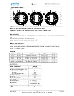
Connecting detectors
Fire detectors are connected directly to the zone line and are powered by this circuit
.
A Detector removal from the zone must be indicated as a fault (EN54/2). For this reason, an
(EOL) 47µF capacitor or 4K7
Ω resistor must be installed in the output connection of the last
detector, between zone positive and negative poles.
At each zone of NFS Supra, 32 Honeywell conventional detectors can be connected; however,
there may be local regulations more restrictive as for the quantity of detectors.
Please read caref
ully the detector’s manuals before connecting them. Check the operating
margins of the zone in the specification section of this manual and the consumption of the
detectors to know the number of detectors that is supported by zone.
-The detectors consumption must not exceed 3mA with an EOL installed..
According to EN54-2, the highest number of detectors supported by a zone is 32. Moreover, the
detectors consumption must not exceed los 3 mA (3000 µA). That means that the number of
detectors to be installed must be calculated depending on their consumption without exceeding
the number of 32 detectors. (For example, if the consumption of detectors 0.2 mA (200 µA), the
maximum detectors number will be 15.
Max. Detectors number <
3000 µA
Each detector consumption (µA)
*Max. Detector amoun is 32 according to EN54
Example:
Max number of detectors by zone, using Eco1000 System Sensor detectors or 800
series detectors from Honeywell: Max. Consumption: 80
A (0,08 mA) in standby.
Max. Number of Detectors
<
3000 µA
= 37
80 µA
Max. number of detectors is 37. However, according to EN54-2 no more than 32 can be
installed.
Max.number of detectors 800 series or ECO1000 from Honeywell will be 32.
47 µF Capacitor
Installation
+ -
+ -
+ -
+ -
+ -
+ -
Alarm Detectors
+ -
A
lar
m
lin
e
Zon
e


