background image

Programmer (Optional) 

44 

DC1010/1020/1030/1040 Product Manual 

8/05 

5.5   Program Configuration Prompts 

5.5.1 Overview 

The prompts to configure the programs will appear after the operation mode prompts. See 
Table 3-3. Also see Table 5-2 for Associated program functions. 

5.5.2 Configuration 

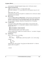
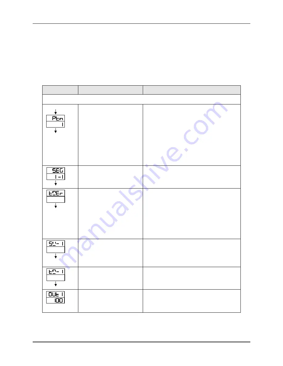
Table 5-3 Program Configuration Prompts 

Displays 

Parameter 

Description 

Start from Operation Mode – See Table 3-3 

SET 

SET 


Program Pattern 

Range: 0-2 

PTN

=1 proceed pattern 1-contains 8 

segments. 

PTN

=2 proceed pattern 2-contains 8 

segments. 

PTN

=0 linking proceed pattern 1 and 2 - total 

16 segments.  

(Please set PTN1 and PTN2 at first, and then 
set PTN to 0) 


SET 


Program Segment Display 

Lower Display = Pattern# 

 Segment# 

Example shown: Pattern 1 

 Segment 1 

Range: Pattern(1,2,0) 

 Segment(1~8) 


SET 


Program timer display 


Range: 99hrs:59min 

Refer to Table 4-4 Functions of Sets to set 
the units of the Timer: 

SET 9.2 = 0 
The unit of Timer is Hour:Minute 

SET 9.2 = 1 
The unit of Timer is Minutes:Seconds 


SET 


Setpoint for Segment 1 

Range:  
LSPL (Lower Setpoint Limit) to  
USPL (Upper Setpoint Limit) 

See Table 4-2 for Limit settings 


SET 


Time Setting for Segment 1 

Range: 0-99 hrs:59 minutes 

Ramp segment* = Changing Setpoint time 
Soak segment** = Fixed Setpoint time 


SET 


Output Limit for Segment 1 

Range: 0 to 100% 

If OUT = 0, program will end 

Summary of Contents for DC1000 SERIES

Page 1: ...Industrial Measurement and Control DC1000 Series Digital Controller Product Manual 51 52 25 113 August 2005 www DataSheet4U net ...

Page 2: ...se items it finds defective The foregoing is Buyer s sole remedy and is in lieu of all other warranties expressed or implied including those of merchantability and fitness for a particular purpose Specifications may change without notice The information we supply is believed to be accurate and reliable as of this printing However we assume no responsibility for its use While we provide application...

Page 3: ... our customers Honeywell Organization WWW Address URL Corporate http www honeywell com Industrial Measurement and Control http www honeywell com imc Telephone Contact us by telephone at the numbers listed below Organization Phone Number United States and Canada Honeywell 1 800 423 9883 Tech Support 1 800 525 7439 Service Asia Pacific Asia Pacific Headquarters 63 2 633 2830 Europe Honeywell PACE Br...

Page 4: ...ecautions for handling electrostatic sensitive devices Protective Earth PE terminal Provided for connection of the protective earth green or green yellow supply system conductor Functional earth terminal Used for non safety purposes such as noise immunity improvement NOTE This connection shall be bonded to protective earth at the source of supply in accordance with national local electrical code r...

Page 5: ... Terminal Connections 12 2 6 3 Wiring Diagrams 13 3 OPERATION 17 3 1 Overview 17 3 2 Operator Interface Overview 17 3 2 1 Displays LEDs and Keys 18 3 3 Mode Access 19 3 3 1 How to move from one mode to another 19 3 4 Operation Mode 20 3 4 1 Key Functions 20 3 4 2 Operation Mode Prompts 20 3 4 3 Control Types 21 3 4 4 Set Point 22 3 4 5 Alarm Functions and Associated Prompts 23 4 CONFIGURATION 24 4...

Page 6: ...R OPTIONAL 41 5 1 Overview 41 5 1 1 Introduction 41 5 2 Programmer Terminologies 41 5 3 Operating Key Functions 41 5 4 Program Functions 41 5 4 1 Program Running Alarm 41 5 4 2 Segment Completion Alarm 42 5 4 3 END Function 42 5 4 4 Linking Function 42 5 4 5 Wait Function 42 5 4 6 Other Functions 43 5 5 Program Configuration Prompts 44 5 5 1 Overview 44 5 5 2 Configuration 44 5 5 3 Program Example...

Page 7: ...e 4 3 Alarm Function Selections ____________________________________________________ 29 Table 4 4 Functions of Sets____________________________________________________________ 35 Table 4 5 Thermocouple Inputs ________________________________________________________ 37 Table 4 6 RTD Inputs ________________________________________________________________ 38 Table 4 7 Linear Inputs __________________...

Page 8: ... Deviation Alarm Alarm Code 02 Alarm release in the first alarming situation ___ 31 Figure 4 5 Lower Limit Deviation Alarm Alarm Code 12 No alarm release in the first alarming situation _ 31 Figure 4 6 Dev Band Breakaway Alarm Alarm Code 03 Alarm release in the first alarming situation ____ 31 Figure 4 7 Dev Band Breakaway Alarm Alarm Code 13 No alarm release in the first alarming situation __ 31 ...

Page 9: ...curity code prevents unauthorized changes Parameters can also be hidden to the user to prevent unauthorized configuration of the unit Various Control Algorithms The DC1000 series of controllers provides several different algorithms PID or ON OFF Control Hear Cool Algorithms with 2 different PID sets Motor Position Control without slidewire feedback Single Phase Control with without zero crossover ...

Page 10: ... following European Council Directive 73 23 EEC the Low Voltage Directive and 89 336 EEC the EMC Directive Conformity of this product with any other CE Mark Directive s shall not be assumed Enclosure Rating Panel mounted equipment IP00 This controller must be panel mounted Terminals must be enclosed within panel Front panel IP65 IEC 529 optionally ...

Page 11: ...AUTION Installation should be performed only by personnel who are technically competent to do so Local Regulations regarding electrical safety must be observed Pre installation Information If the controller has not been removed from its shipping carton inspect the carton for damage then remove the controller Inspect the unit for any obvious shipping damage and report any damage due to transit to t...

Page 12: ...Æ10 Relay Output Contact SPST DC1010 SPDT 1020 1030 1040 3A 240VAC Voltage Output Voltage Pulse 20VDC 20mA Linear Output 4 20mA 0 5V 0 10V 1 5V 2 10V Motor Control Output Three Position Step Control Time proportional motor control Output Others 1ϕ SSR 3ϕ SSR 1ϕ SCR 3ϕ SCR Channel 3 channels optional Mode 17 alarm mode available Alarm Timer Flicker alarm continued alarm on delay timer alarm Output ...

Page 13: ... 0 800 1000 C N 0 0 1200 1300 C T 0 0 400 0 200 0 C 0 0 350 0 C W 0 0 2000 2320 C PL II 0 0 1300 1390 C U 199 9 600 0 200 0 C 0 0 400 0 C TC L 0 0 400 0 800 0 C Pt100 199 9 600 0 400 0 200 0 C 0 0 200 0 400 0 600 0 C JPt100 199 9 600 0 400 0 200 0 C 0 0 200 0 400 0 600 0 C RTD JPt50 199 9 600 0 400 0 200 0 C 0 0 200 0 400 0 600 0 C Linear AN4 AN5 0 50mV 10 50mV 0 20mA 0 1V 0 5V 0 10V 4 20mA 1 5V 2...

Page 14: ...x 96 DIN 1 4 DC1040_ _ Power 90 240 Vac Power DC10_0_ _ 15 50 Vdc Power DC10_1_ _ b b b b 90 240 Vac Power IP 65 DC10_2_ _ 15 50 Vac Power IP65 DC10_3_ _ b b b b 90 240 Vac Power UL Agency Approval DC10_4_ _ 15 50 Vdc Power UL Agency Approval DC10_5_ _ b b b b Program None DC10_ _C_ Program 2 patterns 8 segments per 1 pattern DC10_ _P_ Input RTD DC10_ _ _R TC DC10_ _ _T Linear DC10_ _ _L TABLE I C...

Page 15: ..._ 1 m n RS 485 _ _ 2 m n TABLE III Manual English E Chinese C French F Korean K RESTRICTIONS NOTES Restriction Available Only With Not Available With Letter Table Selection Table Selection b X _ _ c _ 0 1 _ 0 2 d DC10 _ _ _ _ _ 0 1 _ 0 _ _ e DC10_ _ _ _ _ X _ 0 _ 2 _ f DC10_ _ _ _ _ X _ X _ 0 _ g DC10_ _ _ _ _ X _ X _ _ _ X _ X h DC10_ _ _ _ _ 0 _ 0 _ 0 _ i DC10_ _ _ _ _ X _ _ X _ _ j DC10_ _ _ _ ...

Page 16: ...panel using the mounting bracket supplied Adequate access space must be available at the back of the panel for installation and servicing activities Overall dimensions and panel cutout requirements for mounting the controller are shown in Figure 2 1 through Figure 2 4 2 4 2 Overall Dimensions Figure 2 1 Model DC1010 Dimensions Figure 2 2 Model DC1020 Dimensions ...

Page 17: ...Installation 8 05 DC1010 1020 1030 1040 Product Manual 9 Figure 2 3 Model DC1030 Dimensions Figure 2 4 Model DC1040 Dimensions ...

Page 18: ...f the model number It will help later when selecting the proper wiring configuration Side View c d e 1 Put the mounting bracket in the rail on the top bottom of the case 2 Bend the grip of the bracket slide the bracket along the rail until the case is secured against the panel 3 Put the grip of the bracket on the groove to fasten the case to the panel Figure 2 5 Mounting Procedure ...

Page 19: ...on to 100 240 Vac 50 60 Hz or 15 50 Vdc power supply mains It is the user s responsibility to provide a switch and non time delay North America quick acting high breaking capacity Type F Europe 1 2A 250V fuse s or circuit breaker for 100 240Vac operation as part of the installation The switch or circuit breaker should be located close to the controller within easy reach of the operator The switch ...

Page 20: ...ller is on the outside of the case Shielded twisted pair cable are required for all Analog I O Process Variable RTD Thermocouple dc millivolt low level signal mA Digital Output and computer interface circuits 2 6 2 Making Terminal Connections 1 Connection of power supply input terminal Type Round Cable square 1 25 mm 0 049 in Diameter 3 0 3 7 mm 0 118 0 145 in 1 25 5 R1 5 Terminal with tube R 1 25...

Page 21: ...2 3 O UT1 4 5 2 3 O UT1 7 CO M CLO SE O PEN 11 12 G 1 K1 13 14 A B C D 2 3 1 O UT1 5 OUTPUT 7 8 9 10 7 8 9 10 7 8 9 10 A B B Li near RTD TC ALARM 2 3 AL2 AL1 11 12 13 RD SD SG 11 12 13 D D CO M M RS232 CO M M RS485 1 11 6 2 12 7 3 13 8 4 14 9 5 10 AUX OUT 11 12 TRS COMM 4 5 A B C D 2 3 1 11 12 AL1 13 14 G 2 K2 Rel ay Vol t Li near L N Figure 2 6 Model DC1010 Wiring ...

Page 22: ... B Li near RTD TC 4 5 3 12 13 11 7 6 NO NC COM NC NO COM NC NO COM AL1 AL2 AL3 15 16 14 15 16 14 RD SD SG 15 16 14 D D C O M M RS232 C O M M RS485 1 11 2 12 3 13 4 14 5 15 6 16 7 17 8 18 9 19 10 20 12 13 TRS 11 Noise Filter POWER AC 100 240V 50 60Hz DC 15 50V option PV OUTPUT ALARM AUX OUT COMM Rel ay Vol t Li near Rel ay Vol t Li near INPUT2 N L Figure 2 7 Model DC1020 DC1025 Wiring ...

Page 23: ... K2 O UT1 8 11 12 13 14 11 12 14 13 11 12 14 13 A B B Li near RTD TC 9 10 8 4 3 NO NC COM NC NO COM AL2 AL1 10 9 Rem ot e SP 16 17 15 RD SD SG 16 17 15 D D CO M M RS232 CO M M RS485 1 15 8 2 16 9 3 17 10 4 18 11 5 19 12 6 20 13 7 21 14 19 18 TRS Noise Filter POWER AC 100 240V 50 60Hz DC 15 50V option INPUT2 PV OUTPUT ALARM AUX OUT COMM Rel ay Vol t Li near Rel ay Vol t Li near N L Figure 2 8 Model...

Page 24: ...3 K3 17 18 19 20 17 18 19 20 17 18 19 20 A B B Linear RTD TC 4 5 3 12 13 11 7 6 NO NC COM NC NO COM NC NO COM AL1 AL2 AL3 15 16 14 Remote SP 15 16 14 RD SD SG 15 16 14 D D COMM RS232 COMM RS485 32 33 31 RD SD SG 32 33 31 D D COMM RS232 COMM RS485 1 31 11 2 32 12 3 33 13 4 34 14 5 35 15 6 36 16 7 37 17 8 38 18 9 39 19 10 40 20 40 39 TRS Noise Filter POWER AC 100 240V 50 60Hz DC 15 50V option Relay ...

Page 25: ...iew an explanation of the Displays keys and LEDs and Mode access and Operation Modes 3 2 Operator Interface Overview Figure 3 1 is a view of the operator interface See Table 3 1 for a description of Displays LEDs and Keys Also see section 4 5 to allow parameters to be hidden or diplayed 20 0 40 60 80 100 Upper Display Lower Display SET key A M key SHIFT key Up key Down key LEDs Bar Graph Figure 3 ...

Page 26: ...ler is doing automatic tuning AL 1 Status of Alarm 1 AL 2 Status of Alarm 2 AL 3 Status of Alarm 3 MAN When the LED is ON it indicates that the controller is in manual mode PRO When a program is running the LED flickers When a program is suspended the LED is ON When no program is running the LED is OFF Keys Function SET SET key allows moving from one parameter to another or saving a new value of a...

Page 27: ...ons Table 3 2 Mode Change Instructions Step Action 1 Press SET key for 5 seconds it grants access to Configuration 1 mode or return to Operation mode from Configuration 1 mode 2 Press SHIFT key for 5 seconds while pressing SET key first it grants access to Configuration 2 mode or return to Operation mode 3 All parameters related to program configuration will be displayed next to parameters in Oper...

Page 28: ...s set to 0 it means the controller has no output 3 4 2 Operation Mode Prompts Table 3 3 Operation Mode Prompts Displays Parameter Description SET SET PV Display SP Display To change the setpoint value see changing parameter values paragraph 3 4 1 1 Press the SET key to save the value SET SET Output Limit Percentage For limiting the maximum value of Control Output Range 0 to 100 SET SET Auto Tuning...

Page 29: ...tput becomes OFF 0 To prevent the control ouput from flickering too frequently set the hysteresis HYS1 in Operation mode Table 3 3 3 4 3 3 PID Control PID control is the default control type of this controller PID is normally used for three mode control This means that the output can be adjusted somewhere between 100 and 0 It applies all three control actions Proportional P Integral I and Derivati...

Page 30: ...logic observes the speed and direction of the PV signal as it approaches the setpoint and temporarily modifies the internal controller response action as necessary to avoid an overshoot There is no change to the PID algorithm and the fuzzy logic does not alter the PID tuning parameters See Configuration 2 Mode Table 4 2 Press the A M key until you see SET SET Select the Fuzzy code in the lower dis...

Page 31: ...Table 4 3 Alarm Function Selections See Configuration 2 Mode Table 4 2 Define the Alarm timing required for prompts Alt1 Alt2 and Alt3 Range 0 99 min 59 seconds 0 flickering alarm 99 59 continual alarm Other Time delay for alarm See Operation Mode Table 3 3 Enter the deviation value or absolute value for prompts Al1 Al2 and Al3 depending on the Alarm Code selected above See Configuration 2 Mode Ta...

Page 32: ... proportion to the error signal the difference between Process Variable and Setpoint Range 0 200 For On Off Control set P1 0 The only other prompt required for setting is HYS 1 SET SET Main Control OUT 1 I Value Integral Value Integral Regulates the controller s output to the size of the error and the time the error has existed The amount of corrective action depends on the value of proportional G...

Page 33: ...alue Integral Value Same as I1 Configuration SET SET SET Sub Control OUT 2 D Value Derivative Time Same as D1 Configuration SET SET SET Sub Control OUT 2 Cycle of Control Output Same as CYT1 Configuration SET SET SET Sub Control OUT 2 Actuation of Hysteresis Same as HYS1 Configuration SET SET Main Control OUT 1 Gap Control Output is turned off before reaching setpoint Turning Point SP GAP 1 Off OU...

Page 34: ...T change this value without technical assistance SET SET Decimal Point Used to set the position of the decimal point Available for Linear Input only SET SET Lower Setpoint Limit For Example Linear Input 4 20mA when 4mA 0 set the value for the lower limit SET SET SET SET Upper Setpoint Limit For Example Linear Input 4 20mA when 20mA 100 set the value for the upper limit SET SET Input 2 INP2 Lower L...

Page 35: ...ust the linear control output during calibration DO NOT change the value without technical assistance example SET SET Sub Control OUT2 Lower Limit of linear output Used to adjust the linear control output during calibration DO NOT change the value without technical assistance example SET SET Sub Control OUT2 Upper Limit of linear output Used to adjust the linear control output during calibration D...

Page 36: ...ion Range LSPL USPL Used to Bias Process Variable SET SET Unit of PV and SP Selection C F and A linear SET SET Soft Filter Adjusts the PV response time Range 0 05 to 1 00 Larger value faster response SET SET DO NOT change this value SET SET Operation Mode Control Action Heating or Cooling SET SET Control Process PID or Fuzzy SET SET Frequency 50 or 60 Hz CAUTION Make sure the proper frequency is s...

Page 37: ...S Figure 4 6 13 Deviation high low alarm NO Figure 4 7 04 14 Band alarm NO Figure 4 8 Figure 4 9 05 Absolute value high alarm YES Figure 4 11 15 Absolute value high alarm NO Figure 4 12 06 Absolute value low alarm YES Figure 4 13 16 Absolute value low alarm NO Figure 4 14 07 Segment end alarm Use for program model only Paragraph 4 3 4 1 17 Program run alarm Use for program model only Figure 4 15 0...

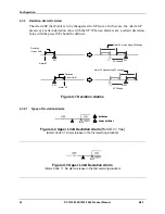
Page 38: ...fined SP1 Deviation Lower limit Alarm SP SP1 SP2 Alarm SP moves along SP change SP Change SP1 Deviation Upper Limit Alarm SP SP1 SP2 Alarm SP moves along SP change SP Change Figure 4 1 Deviation Alarms 4 3 2 1 Types of Deviation Alarms Set Point Alarm Set Point Set Point Alarm Set Point Figure 4 2 Upper Limit Deviation Alarm Hold On Yes Alarm Code 01 Alarm release in the first alarming situation F...

Page 39: ...he first alarming situation Figure 4 6 Dev Band Breakaway Alarm Hold On Yes Alarm Code 03 Alarm release in the first alarming situation Figure 4 7 Dev Band Breakaway Alarm Alarm Code 13 No alarm release in the first alarming situation Figure 4 8 Deviation Band Alarm Hold On Yes Alarm Code 04 Alarm release in the first alarming situation Figure 4 9 Deviation Band Alarm Alarm Code 14 No alarm releas...

Page 40: ...10 Absolute Value Alarm 4 3 3 1 Types of Absolute Value Alarms Figure 4 11 Absolute Upper Limit Alarm Hold On Yes Alarm Code 05 Alarm release in the first alarming situation Figure 4 12 Absolute Upper Limit Alarm Alarm Code 15 No alarm release in the first alarming situation Figure 4 13 Absolute Lower Limit Alarm Alarm Code 06 Alarm release in the first alarming situation Figure 4 14 Absolute Lowe...

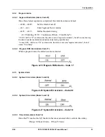
Page 41: ... alarm is enabled activated immediately and last during specified time In case ALD1 ALD3 is not 07 in other words the alarm is not set as segment end alarm the ALT means Time Delay 4 3 4 2 Program RUN Alarm Alarm Code 17 While a program runs the alarm becomes actuated Figure 4 15 Program RUN Alarm Code 17 4 3 5 System Alarm 4 3 5 1 System Error Alarm Alarm Code 08 Figure 4 16 System Error Alarm Co...

Page 42: ...Every value change in each mode allowed LCK 0110 MODE ACCESS Access to Operation Configuration 1 mode allowed VALUE CHANGE Value changes only in Operation mode allowed LCK 0001 MODE ACCESS Access to Operation mode allowed VALUE CHANGE Value change of SP Set Point allowed only LCK 1111 MODE ACCESS Access to Set Up mode allowed LCK 0101 All access value changes prohibited except the change of LCK st...

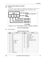
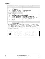
Page 43: ...splayed AT Hidden AL1 Displayed AL2 Hidden SET 1 0 1 0 1 Status of SET 1 Status of SET 2 Status of SET 3 Status of SET 4 SET N0 Press SET key to change SET 0 9 0 Hide 1 Display Set Number Example Set 1 0 1 0 1 OUTL Displayed AT Hidden AL1 Displayed AL2 Hidden Figure 4 18 Display Status 4 5 2 Functions of SETs Table 4 4 Functions of Sets Set Number Function Set Number Function 1 1 OUTL 5 1 CLO2 CHO...

Page 44: ... option Note 1 When SET 8 3 1 the Programmer Controller will initiate the SV value to the current PV value It will be more energy efficient and also decreases the time needed to achieve the desired SV value The remaining time left to reach the SV value will be shown in the parameter TIMR Hence the time of countdown is related to the PV value not related to segment setting CAUTION DO NOT operate SE...

Page 45: ... 0 F 0 600 C 0 1112 F 0 800 C 0 1472 F 0 1000 C 0 1832 F K 0 1200 C 0 2192 F 0 0 200 0 C 0 0 392 0 F 0 0 400 0 C 0 0 752 0 F 0 600 C 0 1112 F 0 800 C 0 1472 F 0 1000 C 0 1832 F J 0 1200 C 0 2192 F 0 1600 C 0 2912 F R 0 1796 C 0 3216 F 0 1600 C 0 2912 F S 0 1796 C 0 3216 F B 0 1820 C 0 3308 F 0 800 C 0 1472 F E 0 1000 C 0 1832 F 0 1200 C 0 2192 F N 0 1300 C 0 2372 F 0 0 400 0 C 0 0 752 0 F 0 0 200 ...

Page 46: ... 199 9 200 0 C 199 9 392 0 F 0 200 C 0 392 F 0 400 C 0 752 F JIS Pt100 0 600 C 0 1112 F 199 9 600 0 C 199 9 999 9 F 199 9 400 0 C 199 9 752 0 F 199 9 200 0 C 199 9 392 0 F 0 200 C 0 392 F 0 400 C 0 752 F DIN Pt100 0 600 C 0 1112 F 199 9 600 0 C 199 9 999 9 F 199 9 400 0 C 199 9 752 0 F 199 9 200 0 C 199 9 392 0 F 0 200 C 0 392 F 0 400 C 0 752 F JIS Pt50 0 600 C 0 1112 F The default of Input Code i...

Page 47: ...mA 0 1V 0 5V 0 10V 1999 9999 10 50mV 4 20mA 1 5V 2 10V 1999 9999 The default of Input Code is AN5 4 20mA for the model of linear input type DC10X0XL XXX XXX X DO NOT change the input type without technical assistance because it requires some hardware changes on the input board in order to select a certain linear input type ...

Page 48: ...Configuration 40 DC1010 1020 1030 1040 Product Manual 8 05 ...

Page 49: ... lets you configure 8 ramp and 8 soak segments to be stored for use as one program or several small programs You designate the end segment to determine where the program is to stop Each segment can be defined as a period of RAMP or SOAK status 5 2 Programmer Terminologies Program A pattern which consists of some segments Segment A RAMP segment or a SOAK segment RAMP A segment with changing SP SOAK...

Page 50: ...rogram running will be ended right after the previous segment is completed Otherwise it will proceed for 8 or 16 segments 5 4 4 Linking Function The program function of DC1000 has 2 program patterns and each program has a maximum of 8 segments You can link these two patterns to obtain a program of 16 segments PTN 0 PTN 1 proceed pattern 1 contains 8 segments PTN 2 proceed pattern 2 contains 8 segm...

Page 51: ...power is lost before the target setpoint is reached upon power recovery the controller powers up with Setpoint Current PV value and it automatically Restarts from setpont current PV value up to the original target setpoint 8 3 0 Program starts from 0 1 Program starts from PV When SET 8 3 1 the setpoint is set to the current PV value and the Program then starts from this value The program will be m...

Page 52: ...ed pattern 1 and 2 total 16 segments Please set PTN1 and PTN2 at first and then set PTN to 0 SET Program Segment Display Lower Display Pattern Segment Example shown Pattern 1 Segment 1 Range Pattern 1 2 0 Segment 1 8 SET Program timer display Range 99hrs 59min Refer to Table 4 4 Functions of Sets to set the units of the Timer SET 9 2 0 The unit of Timer is Hour Minute SET 9 2 1 The unit of Timer i...

Page 53: ...ing for Segment 3 Range 0 99 hrs 59 minutes Ramp segment Changing Setpoint time Soak segment Fixed Setpoint time SET Output Limit for Segment 3 Range 0 to 100 If OUT 0 program will end SET Setpoint for Segment 4 Range LSPL Lower Setpoint Limit to USPL Upper Setpoint Limit See Table 4 2 for Limit settings SET Time Setting for Segment 4 Range 0 99 hrs 59 minutes Ramp segment Changing Setpoint time S...

Page 54: ...it See Table 4 2 for Limit settings SET Time Setting for Segment 7 Range 0 99 hrs 59 minutes Ramp segment Changing Setpoint time Soak segment Fixed Setpoint time SET Output Limit for Segment 7 Range 0 to 100 If OUT 0 program will end SET Setpoint for Segment 8 Range LSPL Lower Setpoint Limit to USPL Upper Setpoint Limit See Table 4 2 for Limit settings SET Time Setting for Segment 8 Range 0 99 hrs...

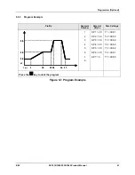
Page 55: ...t Values Time Settings 1 10 12 14 16 17 20 50 90 SP Time 1 10 12 14 16 17 20 50 90 1 10 12 14 16 17 20 50 90 SP Time 1 2 3 4 5 6 7 8 SP 1 20 SP 2 50 SP 3 50 SP 4 90 SP 5 90 SP 6 20 SP 7 0 T 1 00 01 T 2 09 00 T 3 00 02 T 4 00 02 T 5 00 02 T 6 00 01 T 7 00 00 Press the key to start the program Figure 5 1 Program Example ...

Page 56: ...l required NOTE Cold junction compensation failure Service Call required Open the circuit of INPUT 2 sensor Check the wiring Excess of PV over upper limit INPUT 1 Shortage of PV under lower limt INPUT1 Excess of PV over upper limit INPUT2 Shortage of PV under lower limt INPUT2 Check sensor wiring input code Adjust the range of indication Memory RAM failure Service call required Interface failure C...

Page 57: ...derations 11 END Function 42 Error Codes 48 F Frequency 28 Functions of SETs 35 Fuzzy Overshoot Suppression 22 G Gap 25 H Hysteresis 25 Hysteresis for alarms 27 I J Input 1 26 Input 2 26 Input Codes 37 Installation 3 Integral Value 24 25 K Key Functions 20 L Linear Inputs 39 Linking Function 42 Lock 25 34 Lower Limit of Aux output 27 Lower Limit of Linear input 26 Lower Limit of linear output 27 M...

Page 58: ...Programmer Terminologies 41 Proportional Band 24 25 PV Compensation 28 PV Display 20 R Ramp Segment 46 RTD Inputs 38 S Segment Completion Alarm 42 Segment End Alarm 33 Set Point 22 Setpoint for Segment 44 Setpoint Limit 26 Soak Segment 46 Soft Filter 28 SP Compensation 28 SP Display 20 Specifications 4 System Alarm 33 System Error Alarm 33 T Terminal Connections 12 Thermocouple Inputs 37 Three Pos...

Page 59: ......

Page 60: ...Industrial Measurement and Control Honeywell Korea 191 HanGangRo 2ga YongSanGu Seoul Korea 51 52 25 113 Rev 1 0805 Printed in Korea ...

Reviews: