background image

Programming

Honeywell

 • 18

5.2

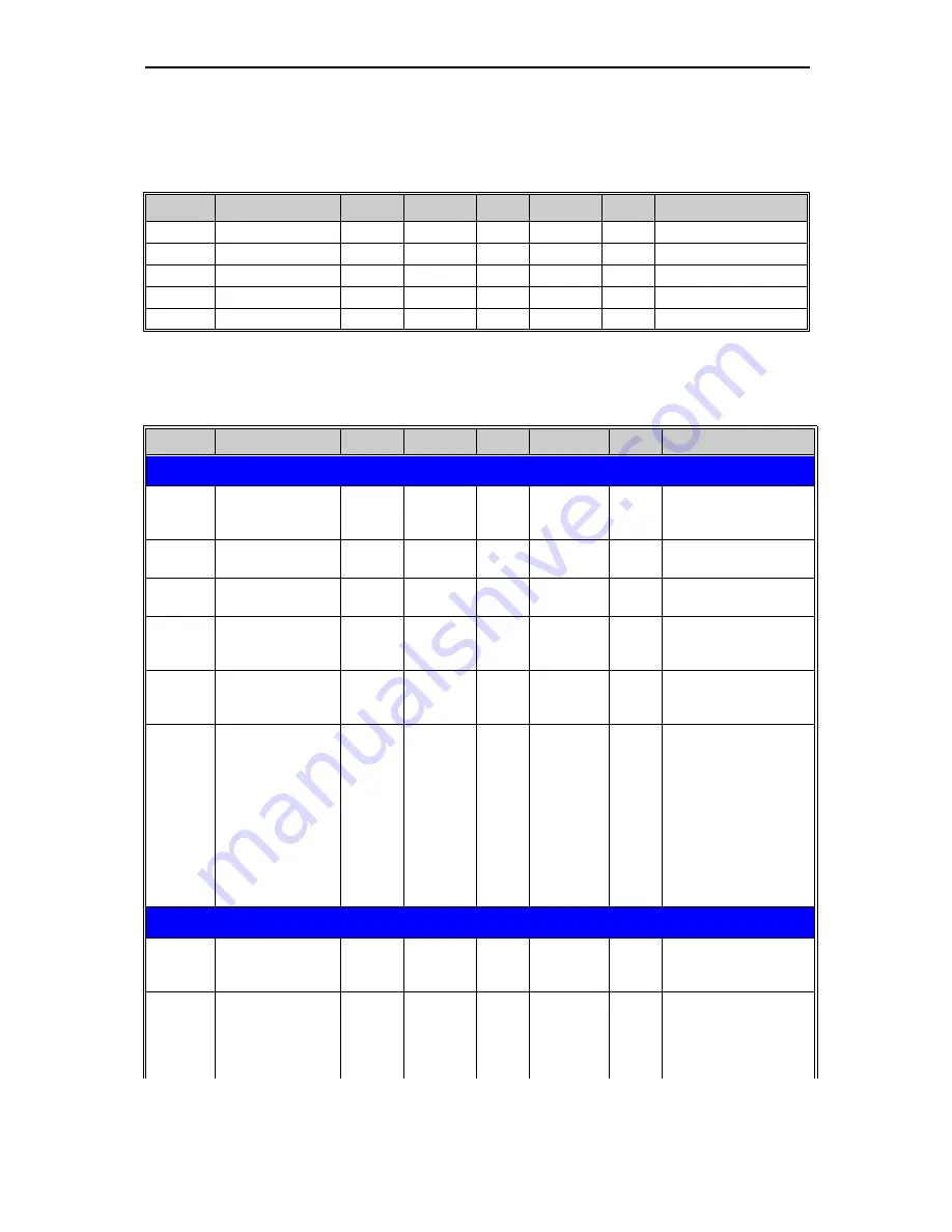
BACnet IP parameters and monitoring values

5.2.1

Ethernet common settings (M5.8.1)

Table 6. Common settings for BACnet IP

5.2.2

BACnet IP settings

Code

Parameter

Min

Max

Unit

Default

ID

Description

P5.8.1.1

IP address mode

See page 23.

P5.8.1.2

IP address

See page 23.

P5.8.1.3

Subnet mask

See page 23.

P5.8.1.4

Default gateway

See page 23.

P5.8.1.5

MAC address

See page 23.

Code

Parameter

Min

Max

Unit

Default

ID

Description

PARAMETERS

P5.8.3.1.1

Instance number

0

4194304

0

Device Object’s instance 
number
0 = Serial number

P5.8.3.1.2

Communication 

time-out

0

65535

s

10

0 = Not used

P5.8.3.1.3

Protocol in use

0

1

0

0 = Not used
1 = Used

P5.8.3.1.4

BBMD IP address

192.168.0.1

BACnet/IP broadcast 
management device IP 
address

P5.8.3.1.5

BBMD UDP Port

1

65535

47808

BACnet/IP broadcast 
management device 
UDP port

P5.8.3.1.6

Time to Live

0

255

s

0

The Time-to-Live value 
is the number of sec-
onds within which a for-
eign device must re-
register with a BBMD. 
The value also applies 
as the interval for trans-
mitting the Register-For-
eign-Device message to 
BBMD device. "0" 
means not in use.

MONITORING VALUES

P5.8.3.2.1

Fieldbus protocol 

status

1

3

1 = Stopped
2 = Operational
3 = Faulted

P5.8.3.2.2

Communication sta-

tus

0.0

99.999

0.0

0-99 Number of mes-
sages with errors
0-999 Number of mes-
sages without communi-
cation errors

Summary of Contents for BacNet protocol

Page 1: ...Honeywell Installation and User Manual BacNet protocol for Variable Frequency Drives ...

Page 2: ...lues 18 5 2 1 Ethernet common settings M5 8 1 18 5 2 2 BACnet IP settings 18 5 3 BACnet MS TP parameter descriptions 20 5 3 1 BACnet MS TP Parameters 20 5 3 2 BACnet MS TP monitoring values 21 5 4 BACnet IP parameter descriptions 23 5 4 1 Ethernet common settings 23 5 4 2 BACnet IP settings 24 5 4 3 BACnet IP monitoring values 24 6 Communications 26 6 1 Object types and properties supported 26 6 1...

Page 3: ...Honeywell 1 ...

Page 4: ...go out if no keypad is attached see the indicators on the cover Wait 5 more minutes before doing any work on the connections of the drive Do not open the cover before this time has expired After expiration of this time use a measur ing equipment to absolutely ensure that no voltage is present Always ensure absence of voltage before starting any electrical work The control I O terminals are isolate...

Page 5: ...ly If the VFD is used as a part of a machine the machine manufacturer is respon sible for providing the machine with a supply disconnecting device EN 60204 1 Only spare parts delivered by Honeywell can be used At power up power brake or fault reset the motor will start immediately if the start signal is active unless the pulse control for Start Stop logic has been selected Futhermore the I O funct...

Page 6: ...c compatibility EMC This equipment complies with IEC 61000 3 12 provided that the short circuit power SSC is greater than or equal to 120 at the interface point between the user s supply and the public sys tem It is the responsibility of the installer or user of the equipment to ensure by consultation with the distribution network operator if necessary that the equipment is connected only to a sup...

Page 7: ...Honeywell 5 Safety ...

Page 8: ...between systems BACnet is an internationally accepted protocol for building automation e g lightning control air conditioning and heating automation and control over a communications network BACnet provides a method by which computer based control equipment from different manu facturers can work together or interoperate For this to be achieved components must be able to exchange and understand BAC...

Page 9: ...Honeywell 7 BACnet general info ...

Page 10: ...ional BACnet MS TP As described in ANSI ASHRAE Stan dards 135 2004 Baud rate 9600 19200 38400 and 76800 baud supports autobaud detection Connections and communications Interface 100BaseTX IEEE 802 3 compatible Data transfer method Ethernet half full duplex Data transfer speed 10 100 MBit s autosensing Protocol BACnet over UDP IP Connector Shielded RJ45 connector NOTE Max length of the non bending ...

Page 11: ...Honeywell 9 BACnet technical data ...

Page 12: ... O terminals may have a dangerous control voltage present even when the drive is disconnected from mains 2 Locate the components that you will need on the VFD to connect and run the BACnet cables Be sure not to plug the Ethernet BACnet IP cable to the terminal under the key pad This might harm your personal computer M4x55 ...

Page 13: ...on on page 8 to its terminal and run the cable through the conduit as shown in Figure 4 NOTE Pay attention that the non bending part of the connector does not exceed 40 mm in length Ethernet connector Ethernet cable run conduit I O terminal see larger picture Grounding bar DIP switches 32 33 12 13 14 15 16 17 18 19 30 B A RS485 terminals 21 22 23 24 25 26 1 2 3 4 5 6 7 8 9 10 11 max 40 mm Ethernet...

Page 14: ... Cut the VFD cover opening for the Ethernet cable protection class IP21 5 Remount the VFD cover NOTE When planning the cable runs remember to keep the distance between the Ethernet cable and the motor cable at a mini mum of 30 cm IP21 Ethernet cable IP21 ...

Page 15: ...o fit in the terminals See picture below Also strip the cable now at such a distance from the terminal that you can fix it to the frame with the grounding clamp Strip the cable at a maximum length of 15 mm Do not strip the aluminum cable shield 4 Then connect the cable to its appropriate terminals on Honeywell SmartDrive standard terminal block terminals A and B A negative B positive See Figure 7 ...

Page 16: ...ast device on the bus the bus termination must be set Locate the DIP switches to the right of the control keypad of the drive and turn the switch for the RS485 bus termination resistor to position ON Biasing is built in the termination resistor See also step 9 on page 15 Cable clamp RS485 AO1 AI2 AI1 OFF ON Current Voltage Current Voltage Current Voltage Bus termination resistor ...

Page 17: ...ble runs remem ber to keep the distance between the fieldbus cable and the motor cable at a minimum of 30 cm 9 The bus termination must be set for the first and the last device of the fieldbus line See picture below See also step 6 on page 14 We recommend that the first device on the bus and thus terminated was the Master device Fieldbus cables BACnet MS TP Bus termination Termination activated Te...

Page 18: ...ault ID Description PARAMETERS P5 7 3 1 1 Baud rate 1 4 bd 1 Communication speed 1 9600 2 19200 3 38400 4 76800 P5 7 3 1 2 Autobauding 0 1 1 Automatic baudrate detection 0 Off 1 On The automati cally detected baud rate is then shown as value of parameter P5 7 3 1 1 P5 7 3 1 3 MAC address 1 127 1 P5 7 3 1 4 Instance number 0 65535 0 Device Object s instance number 0 Automatically gegerated P5 7 3 1...

Page 19: ...umber of mes sages with errors 0 999 Number of mes sages without communi cation errors P5 7 3 2 3 Actual instance number 0 65535 Serial number Shows actual Device Object s instance num ber P5 7 3 2 4 Fault code 0 3 0 0 None 1 Sole Master 2 Duplicate MAC ID 3 Baud rate fault P5 7 3 2 5 Control word hex See chapters 6 2 and 6 3 P5 7 3 2 6 Status word hex See chapters 6 2 and 6 3 Code Parameter Min M...

Page 20: ...tion time out 0 65535 s 10 0 Not used P5 8 3 1 3 Protocol in use 0 1 0 0 Not used 1 Used P5 8 3 1 4 BBMD IP address 192 168 0 1 BACnet IP broadcast management device IP address P5 8 3 1 5 BBMD UDP Port 1 65535 47808 BACnet IP broadcast management device UDP port P5 8 3 1 6 Time to Live 0 255 s 0 The Time to Live value is the number of sec onds within which a for eign device must re register with a...

Page 21: ...rough Ethernet P5 8 3 2 3 Actual instance number 0 65535 Serial num ber Shows actual Device Object s instance num ber P5 8 3 2 4 Control word hex See chapters 6 2 and 6 3 P5 8 3 2 5 Status word hex See chapters 6 2 and 6 3 Code Parameter Min Max Unit Default ID Description ...

Page 22: ...e valid for both masters and slaves The portion of the address space that is actually used for masters in a particular instal lation is determined by the value of the Max_Master property of the Device object It is recommended that MAC address 0 be reserved for use by the MS TP router 255 is re served for broadcasts P5 7 3 1 4 INSTANCE NUMBER The Device Object s Instance number must be unique acros...

Page 23: ...ckages Table 9 P5 7 3 2 3 ACTUAL INSTANCE NUMBER Shows the actual instance number P5 7 3 2 4 FAULT CODE Shows BACnet MS TP fault codes Table 10 P5 7 3 2 5 CONTROL WORD Shows the Control Word received from the bus INITIALIZING Protocol is starting up STOPPED Protocol is timeouted or not used OPERATIONAL Protocol is running FAULTED Major fault in protocol requires restarting If fault remains contact...

Page 24: ...Programming Honeywell 22 P5 7 3 2 6 STATUS WORD Shows the current Status Word that is sent to the bus ...

Page 25: ... from DHCP to Fixed the addresses will read IP 192 168 0 10 Subnet mask 0 0 0 0 Default gateway 0 0 0 0 P5 8 1 2 IP ADDRESS An IP address is a series of numbers like above specific to the device connected to the Inter net P5 8 1 3 SUBNET MASK The network mask marks all the bits of an IP address for the identification of the network and the subnetwork P5 8 1 4 DEFAULT GATEWAY Gateway address is the...

Page 26: ...net IP broadcast management device UDP port P5 8 3 1 6 TIME TO LIVE The Time to Live value is the number of seconds within which a foreign device must re register with a BBMD The value also applies as the interval for transmitting the Register Foreign De vice message to BBMD device 0 means not in use 5 4 3 BACnet IP monitoring values P5 8 3 2 1 FIELDBUS PROTOCOL STATUS Fieldbus Protocol Status tel...

Page 27: ...Honeywell 25 Programming P5 8 3 2 3 CONTROL WORD Shows the Control Word received from the bus P5 8 3 2 4 STATUS WORD Shows the current Status Word that is sent to the bus ...

Page 28: ...are Revision X Application Software Version X Protocol Version X Protocol Revision X Protocol Services Supported X Protocol Object Types supported X Object List X Max APDU Length Accepted X Segmentation Supported X APDU Timeout X Number of ADPU Retries X Max Master X Max Info Frames X Device Address Binding X Database Revision X Preset Value X X Status Flags X X Event State X X Out of Service X X ...

Page 29: ...ssDataOut1 bit 2 0 1 R BV10 fb_ProcessdataOut_01 Bit_3 ProcessDataOut1 bit 3 0 1 R BV11 fb_ProcessdataOut_01 Bit_4 ProcessDataOut1 bit 4 0 1 R BV12 fb_ProcessdataOut_01 Bit_5 ProcessDataOut1 bit 5 0 1 R BV13 fb_ProcessdataOut_01 Bit_6 ProcessDataOut1 bit 6 0 1 R BV14 fb_ProcessdataOut_01 Bit_7 ProcessDataOut1 bit 7 0 1 R BV15 Run Stop CMD Command to start drive FB control is active Stop Run C BV16...

Page 30: ...R Read only W Writeable C Commandable Commandable values support priority arrays relinquish defaults BV28 fb_control_word Bit_13 fb_control_word bit 13 0 1 C BV29 fb_control_word Bit_14 fb_control_word bit 14 0 1 C BV30 fb_control_word Bit_15 fb_control_word bit 15 0 1 C ...

Page 31: ...resetta ble kWh R AV13 Torque Reference Torque Reference R AV14 Temperature Rise Calculated motor tem perature 100 0 nom inal temperature of motor R AV15 fb_ProcessdataOut_01 Application specific 16 bit Resolution 1 R AV16 fb_ProcessdataOut_02 Application specific 16 bit Resolution 1 R AV17 fb_ProcessdataOut_03 Application specific 16 bit Resolution 1 R AV18 fb_ProcessdataOut_04 Application specif...

Page 32: ...its Resolution 1 C AV32 fb_ProcessdataIn_03 Application specific 16 bits Resolution 1 C AV33 fb_ProcessdataIn_04 Application specific 16 bits Resolution 1 C AV34 AnyParam ID ID number that is used in AV35 0 to 65535 resolution 1 W AV35 AnyParam Value Value of ID defined by AV34 32 bits Value W AV36 Fb_Control_Word Lo16 Fixed Control Word First 16 bits 0 15 16 bits Resolution 1 C AV37 Fb_Control_Wo...

Page 33: ...t used Bit Name Value 1 Value 0 Description B0 Ready Ready Not ready Indicates whether the drive is ready or not B1 Run Running Stop Indicates whether the drive is running or stopped B2 Direction Counterclockwise Clockwise Indicates the rotation direc tion of the motor B3 Fault Faulted Not faulted Indicates if a fault is active B4 Alarm Alarm No alarm Indicates if an alarm is active B5 AtReference...

Page 34: ... fault table presents only the faults related to the fieldbus in use 7 1 Typical fault conditions Table 17 Typical fault conditions Fault condition Possible cause Remedy Termination resistor Missing or excessive termination resistor Install termination resistors at both ends of the fieldbus line Cabling Supply or motor cables are located too close to the fieldbus cable Wrong type of fieldbus cable...

Page 35: ...2 5 Set variable AV36 to 1 Check fieldbus parameters Check other fieldbus parameters in menu M5 8 Check selected protocol M5 7 1 1 Check Master s parameters Check configura tions Slave add ress baudrate etc Check termination resistors Check that both ends of the fieldbus line have termination resistors chapter 4 2 Check cabling Check cable for cuts Check correct placement of conductors in terminal...

Page 36: ...1 15 or P3 2 1 Does Master give RUN command Use keypad to monitor variable M5 7 3 2 5 Set variable AV36 to 1 Check fieldbus parameters Check other fieldbus parameters in menu M5 8 Check selected protocol M5 7 1 1 Check Master s parameters Check IP address gateway etc Check cabling Check cable for cuts Check correct place ment of conductors in terminals Other bus devices Check other necessary devic...

Page 37: ...Honeywell 35 Fault tracing ...

Page 38: ...n Menu Quick Setup M1 Rem Ctrl Place P1 15 FieldbusCTRL 2 Make these settings in the master software A Set Control Word to 0 AV36 Fb_Control_Word_Lo16 B Set Control Word to 1 AV36 Fb_Control_Word_Lo16 C Frequency converter status is RUN D Set Reference value to 50 50 00 AV24 Speed Reference E Frequency setpoint is 25 00 Hz if MinFreq is 0 00 Hz and MaxFreq is 50 00 Hz F Set Control Word to 0 AV36 ...

Page 39: ... and no 4 to no 1 Max master is set to 127 Having received the token and sent its data the device with the highest address on the bus in this case 4 will check the bus for new devices by sending a Poll for master message After the first token passing round the Poll for master message is sent to address 5 after the second round time to address 6 and so forth until address 127 is reached Because the...

Page 40: ... xxx Firmware Revision 1 BACnet Protocol Revision 4 Product Description Honeywell SmartDrive HVAC BACnet Standardized Device Profile Annex L BACnet Application Specific Controller B ASC List all BACnet Interoperability Building Blocks Supported Annex K DS RP B DS RPM B DS WP B DS WPM B DM DDB B DM DOB B Segmentation Capability Segmented requests supportedWindow Size Segmented responses supportedWi...

Page 41: ...ice Address Binding Is static device binding supported This is currently necessary for two way communication with MS TP slaves and certain other devices Yes No Networking Options Router Clause 6 List all routing configurations e g ARCNET Ethernet Ethernet MS TP etc Annex H BACnet Tunneling Router over IP BACnet IP Broadcast Management Device BBMD Does the BBMD support registrations by Foreign Devi...

Page 42: ...lephone 49 7031 637 01 Telefax 49 7073 637 493 www ecc emea honeywell com EN2B 0371GE51 R1210 December 2010 2010 Honeywell International Inc Find out more For more information on Honeywell s variable frequency drives and other Honeywell products visit us online at http ecc emea honeywell com ...

Reviews: