MAN0443.P65 Issue 13 Aug 04
5701 Control System
05701-M-5001 A02279
CHAPTER 4 - INSTALLATION INSTRUCTIONS
4 - 19
11.
SENSOR INSTALLATION
11.1
General
Always install the sensors in accordance with the Sensor Operating
Instructions.
In general, sensors for lighter than air gasses should be located at a
high level and sensors for heavier than air gasses should be located at
a low level.
Do not install the sensors:
a.
Where the normal air flow may be impeded.
b.
In corners of rooms where static air pockets may exist.
c.
Near sources of heat such as convector heaters.
Do install the sensors:
a.
As close as possible to the potential source of gas to be detected in
order to give the maximum possible warning.
b.
So that they are accessible for maintenance work.
11.2
Sensor Line Resistance
Sensors should be located such that the line resistance of cable does
not exceed the maximum permitted. The table gives a quick guide to
the maximum cable lengths permitted for specific sensors, when
connected by stranded copper conductor cables of various sizes to a
System 57 running at the minimum dc input voltage.
The figures in the table provide a useful reference guide to maximum
cable lengths, however, in many circumstances longer cable runs can
be used. eg. Where the dc input voltage is higher than the minimum. In
these circumstances a more detailed analysis is required to determine
maximum line resistance.
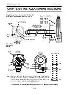
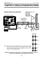
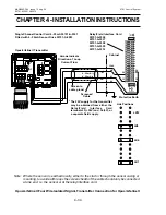
The following sections outline how to calculate the maximum line
resistance for catalytic sensors, loop powered sensors and transmitters
powered from the System 57. See Section 11.3 for a guide on cable
selection.


