7 - 8
MAN0443.P65 Issue 13 Aug 04
5701 Control System
05701-M-5001 A02279
CHAPTER 7 - ENGINEER'S OPERATING
INSTRUCTIONS
6.
ALARM CONFIGURATION AND RELAY TEST
The alarm configuration and relay test operation cycles through eight
different stages, A1, A2, A3, STEL, LTEL, TEST
AI, A2. A3
, TEST
STEL
and
TEST
LTEL
. In the first three stages the alarm LEDs and relays are not
effected. The first five stages are used to set the alarm threshold points
while the last three stages provide a lamp test and relay test function.
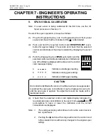
To select the alarm configuration operation, proceed as follows:
(1)
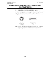
Plug the Engineering Key into the Engineering Card front panel
socket and check that the Unlocked LED ( ) is illuminated.
(2)
Push and hold the required control card
RESET/SELECT
push-
button for approximately 1.5 seconds and check that the selected
control card indicates it has been selected by displaying the select
icon.
(3)
Push the Engineering Card
ALARMS
push-button and check that the
selected control card message display shows A1 for a rising alarm
threshold or A1 for a falling alarm threshold.
(4)
Check that the selected control card digital display indicates the A1
alarm threshold point.
Notes: 1.
The analogue display continues to show the sensor live
measurement.
2.
If an alarm is disabled, '
- - - -
' will be shown on the digital
display and no adjustment will be possible.
(5)
If required, use the and push-buttons to set a new A1 alarm
threshold point.
Note: The threshold level can only be set to a level that is between the
high and low points set in the Control Card configuration.
(6)
When the correct level has been set, and if no more adjustments are
required, push the push-button to set the new level and store this
permanently. Otherwise proceed to Step (7).
Note: If it is required to cancel the procedure at any time without altering
the original setting to the displayed value, press the push button.
(7)
Push the Engineering Card
ALARMS
push-button a second time and

