42
Mounting and Operating Instructions Doorguard for MB panels BUS-2
10.
Operating Instructions
10.1
Overview
The Doorguard can only be operated by authorized persons as follows:
- With key operation
- With ID data carrier
- Via external operating input (e.g. key-operated switch),
- Via the corresponding key at the disable and display module,
- Via corresponding operating function at an operating unit.
Remote controlled enabling (inactivating and activating) using IQ MultiAccess / IQ SystemControl is also possible.
10.2
Operation with key
Turn key clockwise to the limit.
On releasing the key, the key returns into the normal position.
10.3
Operation with ID data carriers
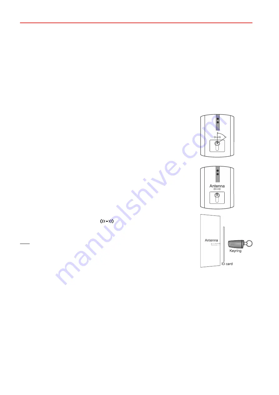
The device has an integrated reader for IK2/proX1 and IK3/proX2 ID data carriers.
The number of possible data carriers depends on the corresponding control panel:
- 561-MB24:
32 data carriers
- 561-MB48:
128 data carriers
- 561-MB100: 1024 data carriers
- MB-Secure: up to 10000 data carriers (depending on license)
The antenna of the receiver module for the ID data carrier is located above the mounting
position for the half cylinder.
The position is marked with the symbol
.
The optimum reading distance is 0 – 3 cm.
Hold ID cards parallel to the housing and keyrings at a right angle.
Note: If the device is programmed to "power-saving mode", then the scanning procedure
could take a bit longer (up to approx. 0.5 sec.).
10.4
Door open monitoring
10.4.1
Function
Door open monitoring is meant to prevent the door from being left open by mistake.
The permissible door open time is programmable from 0 to 2 hours (default setting 3 minutes). A signal sounds in
good time before the door open time expires, indicating that the door should now be closed.
If the door open time is exceeded, an optical and acoustical message are sent to alarm devices.
The device can be programmed in 2 ways to
switch to the active state
after the door is closed:
-
Automatically when the door is closed
or
-
Manually (operation with key or ID data carrier necessary)


