


38
Mounting and Operating Instructions Doorguard for MB panels BUS-2
6.
Installation instructions
6.1
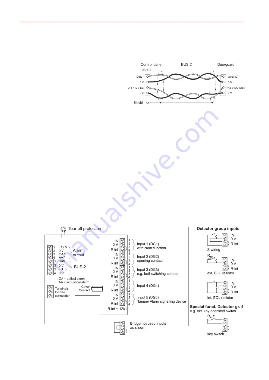
BUS-2 connection
The BUS-2 connecting cable must be a shielded, twisted pair lead with wires routed as follows:
Recommended type of cable:
Shielded telephone cable J-Y(St)Y with lead diameter
of 0.6 mm or 0.8 mm.
The required line cross sections can be found in the
InstalIation Manual of the Intruder alarm control panel
(Chapter "Lines").
6.2
Connection to alarm signalling device
The alarm signalling device is connected via a wired connection (see Chapter 7.2). Four wires are required for
alarm signalling and two wires for tamper monitoring.
6.3
Shielding
A support terminal for the “Shield” of the cable can be used by one of the 3 terminals for free connection (see
connection diagram) in case the BUS-2 connecting cable is installed to another BUS-2 user. In this case, the cable
shields of both BUS-2 connecting cables can be connected to one another at one of the connection terminals.
When using the terminal ensure that the shield connection is as short as possible so that there is no risk of an
unintentional short circuit (if necessary use an insulated flexible tube for the cable shield tracer wire).
7.
Connection diagrams
7.1
Operating device
Details to the function of the detector group inputs see 2.1.