


Mounting and Operating Instructions Doorguard for MB panels BUS-2
33
10
Required software: MB24/48/100 from V18.xx, MB-Secure fromV04.xx (see 1.2.2)
3.
Device set up
3.1
Operating device
3.1.1
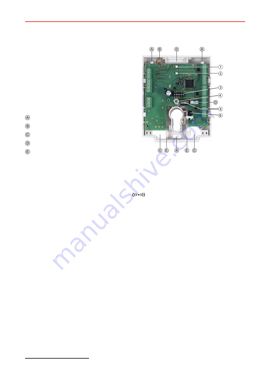
Overview
N
LED geen
O
LED red
P
DIP switch for BUS-2 address
Q
Antenna of the receiver module
R
Cover contact
S
Operating switch for key operation
Fixing holes
Tear-off protection
Cable entry
Cable clip for cable routing
Pull reliefs
3.1.2
Integrated reader
The device has an integrated reader for IK2/proX1 and IK3/proX2 ID data carriers.
The antenna of the receiver module for the ID data carrier is located above the mounting position for the half
cylinder.
The position is marked on the housing with the symbol
.
Operation with the integrated reader is possible irrespective of whether a half cylinder is being used or not.
The reading mode can be set in 2 ways via programming:
-
Power-saving mode:
pulsed reading for a limited time
- Low current consumption, slightly longer reading procedure (up to approx. 0.5 sec.)
-
Standard mode:
10
permanent reading mode:
- short scanning procedure, some more current consumption
3.1.3
Tamper triggered
The housings is equipped with a cover contact
and tear-off protection. If the tamper detector group is triggered in
both the active and inactive state, (e.g. housing cover is lifted), triggering is transmitted to the intruder alarm control
panel as a tamper alarm.