Home Wireless Networks HWN500 Reference Manual Download Page 79

System Administration via the Handset

77

3 5 ( / , 0 , 1 $ 5 <    Y     

digit dialing. If your area does not use 
10-digit dialing, you must delete all area 
codes but one.

Deleting a local area code

Procedure

1.

Press MENU until you reach the screen 
containing the Setup function.

2.

Press 9 (Setup)

3.

Press 2 (Network).

4.

Press 4 (Dialing rules).
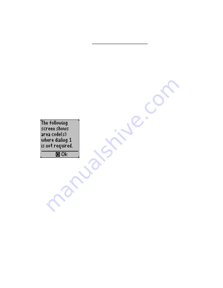
5.

Press 1 (Local area codes).

If your system is set to use 10-digit 
dialing, the handset displays the screen 
shown at left. Press 0 (Okay) to display 
area codes where dialing 1 is not 
required, then use the # and * keys to 
highlight the area code to be deleted.

If your system is not set to use 10-digit 
dialing, the handset displays the local 
area code and asks if you would like to 
make changes. Press 1 (Yes) to make 
changes to the local area code.

6.

Press (Del).

7.

Press 1 (Yes) to confirm the deletion.

When the handset displays the “Area 
code removed” screen, press 0.

Summary of Contents for HWN500

Page 1: ...3 5 0 1 5 Y Printed 11 6 98 Home Wireless Networks HWN500 Network Reference Manual working copy ...

Page 2: ...______________________ System password ________________________________________ If you plan to use your network for voice communications record the number of each incoming telephone line in the spaces below Line 1 _________________________________________________ Line 2 _________________________________________________ Line 3 _________________________________________________ Line 4 _______________...

Page 3: ...cording the Controller Serial Number 14 Choosing a location 15 Attaching rubber feet to Controller base 17 Connecting the incoming telephone lines 18 Installing the battery 20 Connecting the power cord 22 Connecting a device to the E Jack 23 Installing Data Jacks 25 Checking parts 25 System requirements 25 Installation Procedure 26 Installation Worksheet 26 Connecting the Data Jack 28 Running the ...

Page 4: ...e 49 Ending a call 49 Placing a call on hold 49 Retrieving a held call 49 Call Waiting 49 Calling another extension 49 Calling all extensions in the network 49 Redialing the last number called 49 Transferring a call 50 Using the Mute function 50 Making the current call private 50 Caller ID and Directory Services Features 51 Dialing from the Caller ID log 51 Deleting a specific record from the Call...

Page 5: ... the system password 64 Managing devices 66 Adding devices to the network 66 Removing devices from the network 67 Changing a device name 68 Setting outbound line selection options 69 Setting inbound ringing options 70 Setting phone line options 71 Setting Call Forwarding for a particular line 71 Setting Call Privacy for all calls on a particular line 72 Specifying the ring pattern for a particular...

Page 6: ...ying Outbound Settings 84 Editing a location s name 84 Editing a location s number 86 Editing a location s dialing schedule 86 Specifying a line for the outdial 87 Specifying Inbound Settings 88 Turning the internal modem on or off 88 Specifying the incoming line 89 System Administration via your PC 90 Troubleshooting 92 Regulatory 94 Information for general telephones 94 Interference information ...

Page 7: ... 5 3 5 0 1 5 Y Wall Mounting Instructions 101 Mounting the Controller on a wall 101 Mounting the Handset charging cradle on a wall 102 ...

Page 8: ...anywhere within your premises anytime you wish again without having to rewire your building Share PC data peripherals and Internet accounts Not only can you share files and peripherals such as printers scanners etc from networked PCs but your Home Wireless Networks system also allows multiple PC users on the network to share a single Internet account all at the same time Advanced telephone feature...

Page 9: ...stem password to one of your own choosing after adding the first Data Jack or Handset to the system For information on this procedure see Changing the system password on page 61 Network components Controller The Controller is the primary component of your Home Wireless Networks communications system The Controller connects to your incoming telephone lines and controls all communications between de...

Page 10: ... to the network via a Data Jack also allows you to perform system administration tasks from the PC Handset The Handset is an advanced wireless display telephone It can support up to four telephone lines and can also be used for system administration purposes In addition it allows users to see at a glance the status of all lines on the network Phone Jack The Phone Jack allows you to wirelessly conn...

Page 11: ...chen sink laundry tub wash bowl wet basement or swimming pool Unplug this product from the wall outlet before cleaning Do not use liquid cleaners or aerosol cleaners Use a damp cloth for cleaning Do not plug the product back in until it is thoroughly dry 4 Avoid using a telephone other than a cordless one during an electrical storm There may be a remote risk of electric shock 5 Do not use a teleph...

Page 12: ...phone equipment Opening or removing covers may expose you to dangerous voltages or other risks Incorrect reassembly could cause electric shock If service or repair work is required take the unit to a qualified technician 11 Unplug this product from the wall outlet and refer servicing to qualified service personnel under the following conditions The power cord is damaged or frayed Liquid has been s...

Page 13: ...h as rings bracelets and keys The battery or conductor may overheat and cause burns 5 Charge the Handset battery pack provided with or identified for use with this product only in accordance with the instructions and limitations specified for this product 6 Observe proper polarity orientation when installing batteries Preventing static electricity damage The components inside your system are extre...

Page 14: ...roller may not be able to acquire the line for the wireless device When the non Home Wireless Networks device attempts to place or receive a call while a wireless network device is using the same line the wireless device may lose connection to the line Use one of the following suggestions to resolve the problem Do not use the non Home Wireless Networks device during an active call on the Controlle...

Page 15: ... If any parts are missing or broken call your dealer Controller Installation Sequence Use the following steps to install the Controller 1 Record the Controller serial number 2 Choose a location for the Controller 3 Attach protective rubber feet to Controller base unless wall mounting the Controller 4 Connect incoming telephone lines if installing Handsets or Phone Jacks on the network 5 Install th...

Page 16: ...erial number in the space provided on the inside front cover of this manual You will need this information in order to add the first handset or data or phone jack to the network The Controller serial number is located on the inside top surface of the Controller It can be found by removing the Controller cover Refer to the following figures Note Be sure the Controller is unplugged before removing t...

Page 17: ...wall mounted Remember the following points when deciding where to install the Controller The Controller must be placed in an easily accessible location to facilitate battery replacement The Controller should be either wall mounted or placed on a stable horizontal surface such as a desk or countertop Model 95 005 000 SN 9843001 Locating the Controller serial number ...

Page 18: ...o the building Contact a qualified telephone technician or your local telephone service provider to arrange for this service Avoid placing the Controller in the following locations on top of or immediately adjacent to a TV VCR stereo system or personal computer beside a window facing a street with heavy traffic near heat sources such as radiators or air ducts in direct sunlight where it is subject...

Page 19: ...face Note To mount the Controller on a wall refer to the wall mounting instructions on page 101 Procedure Attach the included protective rubber feet to the underside of the Controller as shown in the following illustration Place the unit far enough away from the edge of the desk to minimize the risk of it being knocked off 1 Attaching protective feet to base 2 ...

Page 20: ... on the network from accessing certain lines For single line telephone wiring Use the following procedure if the telephone wiring coming into your building consists of single line wires that is each cable carries only one telephone line Procedure 1 Connect one of the RJ 14 cables from your Controller kit to your primary incoming telephone line Plug the other end of the cable to the Line 1 Connecto...

Page 21: ...ephone lines use the RJ 14 cables supplied with the Controller to plug the primary incoming line Lines 1 and 2 into the Line 1 Connector If you have a second incoming 2 line cable Lines 3 and 4 plug it into the Line 3 Connector Be sure in this instance to leave the Line 2 and Line 4 Connectors empty see the following illustration Connecting single line telephone cables ...

Page 22: ...the Lines 3 and 4 connectors will also illluminate Installing the battery The Controller battery provides back up power to your network in the event of a power outage When the Controller battery needs to be replaced a low battery warning is displayed on the screen of all handsets in the network You should replace the Controller battery as soon as possible when you see this warning Notes Use only n...

Page 23: ...life you should limit use of the network to emergencies only when the power is out It is a good idea to change your Controller batteries at least once a year Procedure Remove the Controller cover Be sure the Controller is unplugged first 1 Opening the Controller ...

Page 24: ... Controller 3 5 0 1 5 Y Insert the 9V battery Note Be sure to observe proper polarity of the connectors Connecting the power cord Procedure Connect the transformer power cord to the Controller 2 Installing the battery 1 ...

Page 25: ... a device to the E Jack The E Jack connector on the Controller allows you to connect existing inside wiring or a single line device such as a standard telephone FAX machine modem or answering machine to the network In the case of a power outage along with Controller battery failure the E Jack provides a connection to the public telephone network and allows the connected device to communicate Conne...

Page 26: ...ed to the E Jack automatically go out on Line 1 Devices connected to the E Jack can break in on any call on Line 1 even a call that has been made Private Telephone company calling services such as Call Waiting Caller ID Distinctive Ringing etc are passed through to the device connected to the E Jack Procedure Plug the cable from the single line device into the E Jack connector Connecting a device ...

Page 27: ...etworked PCs If you have an Internet account you can also use the network as an Internet gateway to provide simultaneous internet access to each PC in the network Checking parts The Data Jack kit should contain the following parts Data Jack 6 Serial Cable 9 pin HWN driver diskette If any parts are missing or broken call your dealer System requirements You must have Windows 95 Windows 98 or Windows...

Page 28: ...Data Jack 3 Run the installation wizard included on the driver diskette Note The Data Jack driver software is provided on a 3 1 2 diskette If you need a different media contact HWN Customer Service at 1 888 WHY WIRE Installation Worksheet You will need to have the following information handy in order to install the Data Jack Be sure to fill in all the blanks on the worksheet before beginning the i...

Page 29: ...and model connected to the Controller 6 For the line attached to the modem described above do you have to dial 9 to reach outside numbers 7 If you subscribe to your telephone company s call waiting service what code do you dial to disable it Part 2 If you have an Internet account and plan to use your Home Wireless Networks communication system to connect to the Internet obtain the following inform...

Page 30: ...e Server 1 ____ ____ ____ ____ 4 Domain Name Server 2 ____ ____ ____ ____ 5 Is there a remote gateway address If yes ____ ____ ____ ____ 6 Dial in Phone Number ______________ Connecting the Data Jack Connect the female end of the Data Jack cable to an available 9 pin serial port on your computer Connect the male end of the cable to the Data Jack Plug the Data Jack into a standard 110v power outlet...

Page 31: ...e driver diskette included with the Data Jack into your PC s floppy drive Click the Start button on the Taskbar Click Run In the Run dialog box click the down arrow to the right of the Open field Click a setup or b setup whichever is appropriate Click OK Follow the on screen prompts to complete the installation 1 2 3 4 5 6 7 8 ...

Page 32: ...ss Networks is voluntarily participating in an industry program to collect and recycle these batteries at the end of their useful life when taken out of service within the United States and Canada The RBRC program provides a convenient alternative to placing spent Ni Cd batteries into the trash or municipal waste streams which is illegal in some areas Please call 1 800 8 BATTERY for information on...

Page 33: ...pack 3 Charge the handset 4 Register the handset with the Controller Attaching rubber feet to charging cradle If you are placing the handset charging cradle on a desk or other horizontal surface attach the included protective rubber feet to the underside of the cradle as shown in the following illustration Note If you are mounting the charging cradle on a wall refer to the wall mounting instructio...

Page 34: ... Home Wireless Networks in the handset For information on ordering replacement batteries call 1 888 WHY WIRE Procedure Remove the battery cover Connect the battery jack and insert the battery pack into place Note Be sure to place the end of the battery pack against not on top of the rubber spacer in the battery well 1 2 ...

Page 35: ...cradle and charge the battery for 24 hours Notes The battery must be installed in the handset in order to recharge it The handset can be placed either face up or face down in the charging cradle The LED on the cradle illuminates when the handset is properly seated Be sure to charge a new handset battery for a full 24 hours For best results and to prolong battery life be sure to fully drain the bat...

Page 36: ... sure to fully charge your new handset battery before beginning the handset registration procedure See page 32 for information on installing and charging the handset battery There are three ways to register a handset with its Controller Self registration registering the handset from itself see the following section Registering the handset from another handset that is already installed on the syste...

Page 37: ...enter the last five digits of your network Controller serial number Press END when finished Note See page 14 for information on locating your Controller serial number You will be asked to confirm that the entered serial number is correct Press 1 Yes to confirm or 2 No to re enter the Controller serial number After confirming that the serial number is correct the handset displays the following scre...

Page 38: ... own choosing as soon as you finish installing and setting up your network The password can be changed via either the handset Setup menu see Changing the system password on page 61 or via a PC connected to a Data Jack Note If the Controller cannot be located the handset displays the following screen Move closer to the Controller and press 0 to restart the handset registration process ...

Page 39: ...dset next displays the following screen Enter a name that identifies the handset with a particular location or individual Note Handset names can be up to 10 characters in length and are entered using the handset keypad Example To enter the name Tim Press 8 one time to add T Press 4 three times to add i Press 6 one time to add m 4 5 ...

Page 40: ... the remaining unwanted text Press END when finished When asked if the entered data is correct press 1 for Yes or 2 for No Note Handset names can be changed at a later date via the Setup menu For details see Changing a device name on page 64 When the handset displays the following screen press 0 OK to continue 6 7 ...

Page 41: ...lays the following screen press 1 YES if you want to add another handset or a data or phone jack to the system Proceed to Step 9 when finished If you do not want to add another handset or a data or phone jack at this time press 2 NO and proceed to Step 10 8 ...

Page 42: ...device Handset serial numbers are located on the underside of the battery cover Data and phone jack serial numbers are located on the plug side of the jack When you have finished adding devices to the network proceed to the next step If this is the first handset you have added to the network and you have not yet specified dialing rules via a PC connected to a Data Jack you will be prompted to defi...

Page 43: ...installation of the first handset Note Dialing Rules tell the system how to dial local and long distance calls for example when to dial 1 before an area code Once established dialing rules can be changed via the handset Setup menu see Defining Dialing Rules on page 70 or via a PC connected to the network via a Data Jack Procedure When the following screen is displayed press 1 YES if you must dial ...

Page 44: ...major metropolitan areas that have more than one area code in a dialing area Example Metro Atlanta Georgia is a good example of a 10 digit dialing area Callers from within any of three Atlanta area codes can place local non toll calls to any other number within those three area codes by dialing xxx xxx xxxx If you pressed 1 YES in the preceding step the following screen is displayed 2 ...

Page 45: ... you pressed 2 NO in Step 1 the following screen is displayed Follow the instructions on the display to enter your local area code After confirming your local area code the following screen is displayed If you must dial 1 to reach any local prefixes press 1 YES and proceed to Step 5 If you do not need to dial 1 to reach any local prefixes press 2 NO and proceed to Step 6 3 4 ...

Page 46: ...xx xxxx no area code to reach If you pressed 1 YES in the preceding step the following screen is displayed Follow the instructions on the display to enter all local prefixes that you must dial 1 to reach When the following screen is displayed press 0 to begin using the handset 5 6 ...

Page 47: ...mmunication system Registering the Phone Jack with the Controller From a handset that is registered with the Controller press MENU until you reach the screen containing the Setup function Select Setup Select Network Select Access Jacks Select Add Enter the serial number of the phone jack being added to the network Press END when finished Note The serial number is located on the plug side of the ja...

Page 48: ... to 10 characters in length Example To enter the name FAX Press 3 three times to add F Press to advance to the next space Press 2 two times to add A Press to advance to the next space Press 9 seven times to add X Press 0 as many times as necessary to delete the remaining unwanted text Press END when finished After confirming that the serial number and name are correct press 0 7 8 ...

Page 49: ... the fax machine standard telephone modem etc into the phone jack Connect the phone jack to the transformer Plug the transformer into a standard 110v power outlet Note The LED on the phone jack connector illuminates when it is receiving power and in communication with the Controller 1 2 3 ...

Page 50: ... See the following example Basic Calling Features Answering an incoming call Press TALK Answering a specific line Select the desired ringing line number Example To answer a call on line 3 press 3 Making a call on the first available line 1 Press TALK or press the number associated with a particular line 2 When you hear dial tone dial the desired number ...

Page 51: ...call will be placed on hold Press FLASH again to return to your original call You can then toggle between the two calls using FLASH Note You must subscribe to your telephone company s Call Waiting service in order to use this feature Calling another extension Press the desired extension number Example To call extension 12 press 12 Calling all extensions in the network 1 Press MENU until you reach ...

Page 52: ... hear you 1 While on a call press MENU until you reach the screen containing the Mute function 2 Select Mute to toggle the Mute function on and off Making the current call private While on a call you can prevent other devices on the network except one connected to the Controller E jack from accessing that line 1 Press MENU until you reach the screen containing the Private feature 2 Select Private ...

Page 53: ...00 Personal Directory entries Entries stored in the Personal Directory are available only to the handset that stored them Dialing from the Caller ID log 1 Press MENU until you reach the screen containing the Caller ID function 2 Select Caller ID from the list of menu options 3 Scroll through the Caller ID records until the desired entry appears 4 Press 5 to dial the number Deleting a specific reco...

Page 54: ...rom the Caller ID log Saving a Caller ID record to the Directory 1 Press MENU until you reach the screen containing the Caller ID function 2 Select Caller ID from the list of menu options 3 Scroll through the Caller ID records until the desired entry appears 4 Press 6 to save the Caller ID information to the Directory 5 If you have the Key System Software Package you will be prompted to press 1 to...

Page 55: ...ctory from the list of menu options If you have the Key System software package you will be prompted to press 1 to reach the System Directory or 2 to reach the Personal Directory See note regarding Directory Services on page 51 3 Select the desired Directory category 2 ABC 3 DEF etc 4 Locate the desired Directory entry 5 Press 5 to dial the number ...

Page 56: ...e Package you will be prompted to press 1 for the System Directory or 2 for the Personal Directory See note regarding Directory Services on page 51 3 Press 0 to add an entry 4 Use the keypad to enter the desired name Example To enter the name Tim Press 8 one time to add T Press to advance to the next space Press 4 three times to add I Press to advance to the next space Press 6 one time to add M Pr...

Page 57: ...ct Directory from the list of menu options If you have the Key System Software Package you will be prompted to press 1 for the System Directory or 2 for the Personal Directory See note regarding Directory Services on page 51 3 Select the desired Directory category 4 Locate the desired Directory entry 5 Press 9 to delete the record from the Directory ...

Page 58: ...creen containing the Conference function 3 Select Conference from the list of menu options Adding another member to a Conference Call 1 Place all parties on hold 2 Press MENU until you reach the screen containing the conference function 3 Press 1 to add a member 4 Press to scroll through the available parties 5 When the desired party is highlighted press 0 OK to add the party to the conference Dro...

Page 59: ...ence Call press MENU until you reach the screen containing the Conference function 2 Select Conference from the list of menu options 3 Press 2 to drop a member 4 Press to scroll through the available members 5 When the desired member is highlighted press 0 OK to drop the member from the conference ...

Page 60: ...on 2 Select Volume from the list of menu options to adjust the handset volume up and down Adjusting the Ringer Volume 1 Press MENU until you reach the screen containing the Ringer volume 2 Select Ringer from the list of menu options to adjust the handset volume up and down Scrolling through the menus When in menu mode press END to return to the previous screen ...

Page 61: ...Example To locate extension 12 press 12 Option 2 If you don t know the extension number of the missing handset you can use another handset to cause all handsets in the network to ring 1 Press MENU until you reach the screen containing the Extensions menu item 2 Press 7 Extensions 3 Scroll through the displayed items until Ring all is highlighted 4 Press 0 Ring all ...

Page 62: ...n disabled for a particular handset Call Forwarding All calls to your phone number will be forwarded as specified Call Waiting If you are on a call and another call comes in on that line you will hear a Call Waiting tone on your handset To answer the waiting call press FLASH Your original call will be placed on hold Press FLASH again to return to your original call You can then toggle between the ...

Page 63: ... for a particular extension via the Setup menu Voice Mail If the Voice Mail feature is activated on your system when a voice mail message waiting signal is sent by the telephone company all handsets in the network will display a Message Waiting Line x message when on the Idle screen Note For information on activating the Voice Mail feature on your network see Setting voice mail options on page 78 ...

Page 64: ...ware version Change system password Network Setup Add remove or configure Handsets or Phone and Data Jacks including editing names and specifying lines for inbound ringing and outbound dialing Set Call Forwarding Call Privacy Ring Pattern or Tone Pulse Dialing for each line Define dialing rules local area code s 10 digit dialing area codes local and or long distance access codes when dialing from ...

Page 65: ... not and specify which line the modem should answer on General System Info Setting the time and date When there is no activity on outside lines the idle screen on your handset displays the date time and day of the week If you subscribe to your local telephone company s Caller ID service the system time and date is reset with each incoming Caller ID call If you do not subscribe to Caller ID service...

Page 66: ... the month Press 5 to increment the date Press END Verifying the system software version You can verify your system s software version using the following procedure Procedure 1 Press MENU until you reach the screen containing the Setup function 2 Press 9 Setup 3 Enter your system password then press END 4 Press 1 General 5 Press 2 System Info Changing the system password You may find it necessary ...

Page 67: ...Passwords must be a 4 digit number Write your password down and keep it in a safe place You will need it to perform all system administration tasks Procedure 1 Press MENU until you reach the screen containing the Setup function 2 Press 9 Setup 3 Enter your system password then press END 4 Press 1 General 5 Press 3 Password 6 Enter the current password then press END 7 Enter the new password then p...

Page 68: ...ting to use a new handset See page 32 for information on installing and charging handset batteries Procedure 1 Press MENU until you reach the screen containing the Setup function 2 Press 9 Setup 3 Enter your system password then press END 4 Press 2 Network 5 Press 1 if adding a handset or 2 if adding a data or phone jack 6 Press 1 Add 7 Enter the serial number of the device being added 8 Enter the...

Page 69: ...rity measure to remove a device that has been lost Procedure 1 Press MENU until you reach the screen containing the Setup function 2 Press 9 Setup 3 Enter your system password then press END 4 Press 2 Network 5 Press 1 if removing a handset or 2 if removing a data or phone jack 6 Press 2 Remove 7 Enter the extension number of the device to be removed Note You can also use and to scroll through the...

Page 70: ...he following procedure Procedure 1 Press MENU until you reach the screen containing the Setup function 2 Press 9 Setup 3 Enter your system password then press END 4 Press 2 Network 5 Press 1 for a handset or 2 for an data or phone jack 6 Press 3 Configure 7 Enter the extension number of the device to be renamed Note You can also use and to scroll through the entries When the desired device is high...

Page 71: ...ns 10 11 and 12 and four phone lines One of the handsets Extension 11 is assigned to a warehouse worker You do not want that person to be able to access Line 3 which you want to keep free for your sales group By turning off outbound dialing on Line 3 from Extension 11 you prevent the warehouse worker from placing calls on Line 3 Procedure 1 Press MENU until you reach the screen containing the Setu...

Page 72: ...nd calls Setting inbound ringing options Inbound Ringing options determine which extensions will ring during incoming calls on each line If desired you can restrict certain extensions from ringing when calls come in on a particular line Example You have three handsets on Extensions 10 11 and 12 and four phone lines One of the phone lines Line 3 is your 800 sales line You do not want the extension ...

Page 73: ...gle the desired lines on or off by pressing the corresponding line number A check mark indicates that incoming calls on that line will ring the extension Setting phone line options Setting Call Forwarding for a particular line Your Home Wireless Networks communications system allows you to forward incoming calls on a specific line to another external phone number If desired a different external Ca...

Page 74: ...mmunications system allows you to specify that all calls on a particular line be Private This means that other devices on the network except one connected to the Controller E jack cannot listen in or break in on the call Note Once turned on for a particular line Call Privacy will remain in effect for that line until turned off If you wish to make only the current call Private see Making the curren...

Page 75: ...r instance and you want to be able to distinguish incoming calls on that line from other incoming calls Procedure 1 Press MENU until you reach the screen containing the Setup function 2 Press 9 Setup 3 Enter your system password then press END 4 Press 2 Network 5 Press 3 Lines 6 Select the desired line number 7 Select 3 Ring pattern 8 Select one of the five ringing pattern options Note If you subs...

Page 76: ...ss 9 Setup 3 Enter your system password then press END 4 Press 2 Network 5 Press 3 Lines 6 Select the desired line number 7 Press 4 Tone to toggle between Tone and Pulse dialing Defining Dialing Rules Dialing Rules tell the system how to dial local and long distance calls for example when to dial 1 before an area code These rules were established during installation of the first handset unless spe...

Page 77: ...ocal area code settings Procedure 1 Press MENU until you reach the screen containing the Setup function 2 Press 9 Setup 3 Press 2 Network 4 Press 4 Dialing rules 5 Press 1 Local area codes 6 If your system is set to use 10 digit dialing the handset displays the screen shown at left Press 0 Ok to display area codes where dialing 1 is not required If your system is not set to use 10 digit dialing th...

Page 78: ...al area code and asks if you would like to make changes Press 1 Yes to make changes to the local area code 6 Press 1 Add 7 Enter the new local area code Press END when finished 8 Press 1 Yes to confirm that the new area code is correct or 2 No to re enter the new area code 9 Press 0 Ok when you have finished adding area codes 10 You will be asked if 10 digit dialing is required at the new location...

Page 79: ...area codes If your system is set to use 10 digit dialing the handset displays the screen shown at left Press 0 Okay to display area codes where dialing 1 is not required then use the and keys to highlight the area code to be deleted If your system is not set to use 10 digit dialing the handset displays the local area code and asks if you would like to make changes Press 1 Yes to make changes to th...

Page 80: ...ou reach the screen containing the Setup function 2 Press 9 Setup 3 Press 2 Network 4 Press 4 Dialing rules 5 Press 2 Within area rules 6 When the screen shown above is displayed press 0 Ok 7 The handset displays all local prefixes where dialing 1 is required Adding a 1 local prefix Procedure 1 Press MENU until you reach the screen containing the Setup function 2 Press 9 Setup 3 Press 2 Network 4 ...

Page 81: ...o the list Deleting a 1 local prefix 1 Press MENU until you reach the screen containing the Setup function 2 Press 9 Setup 3 Press 2 Network 4 Press 4 Dialing rules 5 Press 2 Within area rules 6 When the screen above is displayed press 0 Ok 7 The handset displays a screen similar to the one shown at left 8 Use the and keys to highlight the prefix you want to delete When the desired prefix is highl...

Page 82: ...wing access code settings Procedure 1 Press MENU until you reach the screen containing the Setup function 2 Press 9 Setup 3 Press 2 Network 4 Press 4 Dialing rules 5 Press 3 Behind PBX 6 To view the local access code setting press 1 To view the long distance access code setting press 2 Defining an access code Procedure 1 Press MENU until you reach the screen containing the Setup function 2 Press 9...

Page 83: ...he Hold Recall Timer determines how long a call will remain on hold before a reminder ring sounds on the extension that placed it on hold When a held call recalls back to the extension the user hears a ring tone and the handset displays Recall Line X You can choose from 5 different timer settings No recall 20 seconds 1 minute 2 minutes 3 minutes Procedure 1 Press MENU until you reach the screen co...

Page 84: ...sferring extension When a transferred call recalls to the transferring extension the user hears a ring tone and the handset displays Recall Line X You can choose from 5 different timer settings No recall 20 seconds 1 minute 2 minutes 3 minutes Procedure 1 Press MENU until you reach the screen containing the Setup function 2 Press 9 Setup 3 Enter your system password then press END 4 Press 2 Networ...

Page 85: ...nes Line Setup and also tell the network which detection method to use Detection Method Line Setup Procedure 1 Press MENU until you reach the screen containing the Setup function 2 Press 9 Setup 3 Enter your system password then press END 4 Press 3 Voice Mail 5 Press 1 Line Setup 6 Press the desired line number to toggle message waiting detection on and off A checkmark indicates that message waiti...

Page 86: ...r contains an internal modem that can be used to place data calls to remote modems and to receive pre arranged inbound troubleshooting calls from Home Wireless Networks Tech Support Specifying Outbound Settings Up to five separate locations may be programmed for outbound dialing The first location is set by default to Home Wireless Networks Tech Support Other options could include dialing a remote...

Page 87: ...e Press END when finished Example To enter the name News Press 6 as many times as necessary to add N Press to advance to the next space Press 3 as many times as necessary to add e Press to advance to the next space Press 9 as many times as necessary to add w Press to advance to the next space Press 7 as many times as necessary to add s Press to advance to the next space Press END 8 Press 1 Yes to ...

Page 88: ...hen press END 4 Press 4 Internal Modem 5 Press 1 Outbound Settings 6 Select the location to be modified 7 Press 2 Edit number 8 Enter the desired number 9 Press END when finished Editing a location s dialing schedule Procedure 1 Press MENU until you reach the screen containing the Setup function 2 Press 9 Setup 3 Enter your system password then press END 4 Press 4 Internal Modem 5 Press 1 Outbound...

Page 89: ... Press 3 as many times as necessary to specify the desired start time Press 4 as many times as necessary to specify the desired ending time 9 Press END when finished Specifying a line for the outdial Procedure 1 Press MENU until you reach the screen containing the Setup function 2 Press 9 Setup 3 Enter your system password then press END 4 Press 4 Internal Modem 5 Press 1 Outbound Settings 6 Selec...

Page 90: ... Networks Tech Support to dial into your system at a pre arranged timefor troubleshooting purposes Note Since this procedure will cause the modem to answer the next incoming call on the specified line you should not turn this setting on unless so directed by Home Wireless Networks Tech Support Turning the internal modem on or off Procedure 1 Press MENU until you reach the screen containing the Set...

Page 91: ...taining the Setup function 2 Press 9 Setup 3 Enter your system password then press END 4 Press 4 Internal Modem 5 Press 2 Inbound Settings 6 Press 2 Choose Line 7 Select the desired line Remember that if internal modem answer is toggled ON the next incoming call on the specified line will be answered by the Controller s internal modem ...

Page 92: ... a PC connected to a Data Jack Note You must have an Internet browser such as Netscape or MS Internet Explorer installed on your PC Procedure 1 Launch your Internet browser 2 Type in the following URL 3 When the Home Wireless Networks screen appears select User Setup 4 Select the desired setup category General Set system time date View software version Change system password Network Setup ...

Page 93: ...it dialing area codes local and or long distance access codes when dialing from behind a PBX or Key system Set Hold Recall and Transfer Recall system timers Voice Mail Turn message waiting detection on or off for each line Specify message detection method Internal Modem Specify outbound information such as location name and number dialing schedule and line to be used for the outdial Specify inboun...

Page 94: ...ce and a network device attempt to use the line at the same time If the non network device is in on an active call when the network device attempts to use the same line the Controller may not be able to acquire the line for the wireless device If the non network device initiates or receives a call while a wireless network device is using the same line the Controller and wireless device may lose co...

Page 95: ...y on page 20 for information on this procedure You forgot your system pasword You can reset your system to the default of 4961 by disconnecting the Controller power cord and removing the Controller battery then reinstalling the battery and reconnecting the power Remember to change the password to one of your own choosing as soon as the network is operational again See Changing the system password ...

Page 96: ...xcessive RENs on the telephone line may result in the devices not ringing in response to an incoming call In most but not all areas the sum of the RENs should not exceed five 5 0 To be certain of the number of devices that may be connected to a line as determined by the total RENs contact the local telephone company 5 If your equipment causes harm to the telephone network the telephone company wil...

Page 97: ...s and or making test calls to emergency numbers 1 Remain on the line and briefly explain to the dispatcher the reason for the call 2 Perform such activities in off peak hours such as early morning or late evenings Caution Your are cautioned that any changes or modifications not expressly approved in the product documentation could void your authority to operated this equipment Interference informa...

Page 98: ...try to correct the interference by one or more of the following measures Reorient or relocate the receiving antenna Increase the separation between the equipment and receiver Connect the equipment to an outlet on a circuit different from that to which the receiver is connected Consult the dealer or an experienced radio TV technician for help This device complies with Part 15 of the FCC Rules Opera...

Page 99: ...tive range 500 1000 feet Number of devices allowed on network Handsets Data Jacks and or Phone Jacks 12 6 can be active at any one time Size 8 5 x 4 75 x 2 25 Weight Channels 37 Bit Rate Ambient temperature range 22 F to 122 F Humidity 20 to 90 non condensing Power Source 7 2v DC via external transformer 9v alkaline battery backup ...

Page 100: ...to 122 F Humidity 20 to 90 non condensing Power Source 3 cell AA rechargeable Ni Cd battery pack Charging Cradle Transformer 9v 100mA Size 4 5 x 2 75 x 1 25 Weight 14 oz Connectors One DB 9 Female Channels 7 Channel Data Rate 6 x 80 Kbits sec each direction Ambient temperature range 32 F to 122 F Humidity 20 to 90 non condensing Power Source 100v AC power line ...

Page 101: ...hone Jack Size 4 5 x 2 75 x 1 25 Weight 14 oz Connectors One RJ 14 Channels 7 Channel Data Rate 6 x 80 Kbits sec each direction Ambient temperature range 32 F to 122 F Humidity 20 to 90 non condensing Power Source 100v AC power line ...

Page 102: ...100 Warranty Information 3 5 0 1 5 Y Warranty Information ...

Page 103: ...ossmarks centered on the stud and mark through the center of each crossmark with a pencil or other sharp pointed object Insert the mounting screws through the wallboard and into the stud at the marked locations Leave enough of the screw protruding to hold the Controller Position the Controller against the wall so the mounting screws align with the holes on the underside of the Controller base Slid...

Page 104: ...gh the center of each crossmark with a pencil or other sharp pointed object Insert the mounting screws through the wallboard and into the stud at the marked locations Leave enough of the screw protruding to hold the cradle Connect the handset AC adaptor to the charging cradle and route the adaptor cord through the channel in the base Position the cradle against the wall so the mounting screws alig...

Page 105: ...late when mounting the Controller on a wall To mark the positions of the mounting screws hold the template against the wall with the crossmarks centered on a wall stud Push a pencil or pen point through the center of each crossmark to mark the wall ...

Page 106: ...Template Use this template when mounting the Handset charging cradle on a wall To mark the positions of the mounting screws hold the template against the wall with the crossmarks centered on a wall stud Push a pencil or pen point through the center of each crossmark to mark the wall ...

Page 107: ......

Page 108: ... 1998 Home Wireless Networks Inc All rights reserved 3145 Avalon Ridge Place Suite 200 Norcross GA USA 30071 888 WHY WIRE www homewireless com Part Number 84 0004 000 Printed in USA ...

Reviews: