background image

90 -


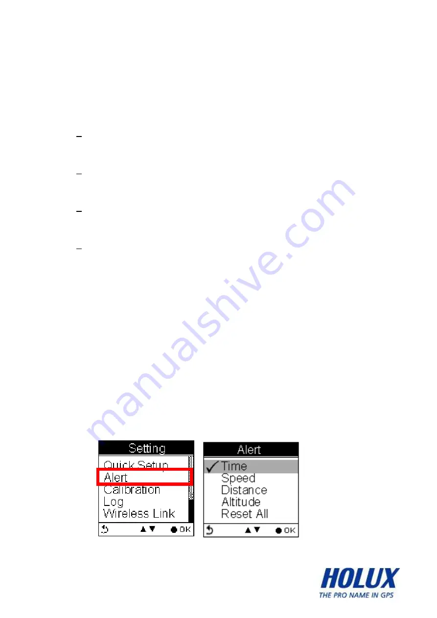
Alert   

The Alert function can be set for 

time

speed

distance

 and 

altitude


Time Alert 

- appears only when the pre-determined time is reached. 


Speed Alert 

-  appears only when the pre-determined speed is reached. 


Distance Alert 

- appears only when the pre-determined distance is reached. 


Altitude Alert 

- appears only when the pre-determined altitude is reached.   


You can press any key to disable the alert message. 


To Set Alerts   

1.  Press the Menu button to enter Main Menu. 

2.  Go to Setting 

 Alert. 

3.  Select Time, Speed, Distance or Altitude to open 

submenu. 


To Set Time Alert   

Summary of Contents for GPSPORT 260 PRO

Page 1: ... 1 GPSport 260 Pro User s Guide ...

Page 2: ...ter in a wet environment When hands and feet are wet do not touch the power adapter While using the power adaptor ensure that the area is well ventilated Do not let paper or other material cover the power adaptor as this will interfere with cooling Do not use the power adaptor whilst it is in a bag Do not attempt to repair the device If this device is damaged or is in a wet environment replace the...

Page 3: ...les These limits are designed to provide reasonable protection against harmful interference in a residential installation This equipment generates uses and can radiate radio frequency energy and if not installed and used in accordance with the instructions may cause harmful interference to radio communications However there is no guarantee that interference will not occur in a particular installat...

Page 4: ... 4 Connect the equipment into an outlet on a circuit different from that to which the receiver is connected Consult the dealer or an experienced radio TV technician for help ...

Page 5: ...any interference received including interference that may cause undesired operation For product available in the USA Canada market only channel 1 11 can be operated Selection of other channels is not possible RF Exposure Warning This equipment must be installed and operated in accordance with provided instructions and the antenna s used for this transmitter must be installed to End users and insta...

Page 6: ...NT 19 WEARING HRM 21 INSTALLING CADENCE 23 INSTALLING SPEED SENSOR 26 REPLACING THE BATTERY OF CADENCE SPEED SENSOR 30 DOWNLOADING TRACK LOGS 32 Installing ezTour Plus 32 Starting ezTour Plus 36 Starting ezTour Planner 37 Connecting to a PC 38 Introduction of 9 Function Modes 39 MAIN MENU 39 SPORT MODE 40 PLOT MODE 47 FOLLOW COURSE MODE 52 TRAINING 60 Training HRM 60 Training Cadence 62 ...

Page 7: ...260 PRO 79 TURNING OFF GPSPORT 260 PRO 79 INITIAL SETUP 79 TURNING ON OFF BACKLIGHT 79 STARTING STOPPING LOGGING 81 Auto Start Logging 81 BASIC OPERATION 82 Quick Menu 82 Basic Operation without Setting 84 Speed Meter 84 STATUS ICONS 86 Setting Up GPSport 260 Pro 87 QUICK SETUP 88 Sport Mode 88 ALERT 90 To Set Alerts 90 To Set Time Alert 90 To Set Speed Alert 91 ...

Page 8: ... Start Logging 100 Pause Logging 101 WIRELESS LINK 102 Activate Wireless Link 102 Scan 103 Connect and Detect 104 About Wheel Size 104 Setting Wheel Size 105 GENERAL SETTING 108 User Profile 108 Set Backlight 109 Auto Flip Page 110 Memory Mode 110 Auto Power Off 111 SYSTEM SETTING 111 Delete all log 112 Time Format 112 Time Zone 112 Unit 113 Language 114 ...

Page 9: ...ZTOUR PLUS 119 FUNCTIONS OF EZTOUR PLANNER 119 FEATURES OF EZTOUR PLUS 119 Normal Care and Maintenance 121 Keep dry 121 Do not drop the unit 121 Avoid sudden temperature changes 121 Keep away from strong magnetic fields 121 Operating temperature 121 Avoid exposure to sunlight 121 Cleaning the screen 122 Do not disassemble 122 Storage 122 Specifications 123 ...

Page 10: ...exercising Plus the built in 3D compass and barometer sensors make it a perfect gadget for outdoor lovers to find their direction and altitude One of its simplest functions is to work as a pedometer for everyday exercise measurer and motivator The GPSport 260 Pro is bundled with a set of powerful software called ezTour Plus and ezTour Planner The former helps users with their health fitness manage...

Page 11: ... to 20 locations and supports return to starting point TripStart automatically records the first GPS fixed location when power on Can simulate an analog speedometer and use a large font display 3 sport modes for calorie calculations Track Log function can start recording after satellite fix Generate QR code for current coordination Supports metric imperial and nautical measurements Supports 12 hou...

Page 12: ... 12 Parts and Functions Front View 1 5 LCD screen OK Up Down Right Left button Backlight Exit Power Start Pause ...

Page 13: ... Function Power button Press to pause resume log when the device is turned on Press for 3 seconds to power on off the unit Exit Backlight Exit to previous level of menu Press for 3 seconds to turn on off the backlight Mini USB Port ...

Page 14: ... 14 5 Direction OK Use Left Up Right and Down to select an option Press the OK button in the middle to confirm selection ...

Page 15: ...owing accessories are included in the box Please contact your supplier immediately if there are any missing items GPSport 260 Pro USB cable Quick Guide AC Adapter Warranty Card CD ROM including ezTour Plus ezTour Planner and documents for user manuals ...

Page 16: ... 16 Bicycle Mounting Kit Pouch ...

Page 17: ... 17 Optional Accessories Heart Rate Monitor HRM set Cadence set containing cadence sensor and magnetic Speed sensor set containing speed sensor and magnetic ...

Page 18: ...utlet When charging the Power indicator shows After charging is completed the Power indicator shows If the power indicator shows while charging it means the charging is automatically disabled because of circuit protection at high temperature Note Do not charge the device at high temperature otherwise the charging may not be performed or the lithium battery can not be fully charged ...

Page 19: ...e Mount You can install the bike mount and the GPS on the left or right side of the handlebar or on the stem 1 Attach the bracket to the bracket holder 2 Thread the two cable ties through the slots of the bracket holder ...

Page 20: ...under the bike mount and attach the bike mount securely to the bike stem using the two cable ties 4 Slide in the GPS on top of the bike mount until it snaps into place Note Cable ties are reusable Press here to release the device ...

Page 21: ...ter conductivity Adjust the length of the elastic chest strap so that it will not fall off when used The HRM comes in two parts the HRM sensor itself and the chest strap Attach the sensor to the chest strap with the mark facing up as shown There are two conductive rubbers on the chest strap slightly moisten them to have better conductivity Adjust the length of the chest strap to fit your chest cir...

Page 22: ... 22 Wrap the chest strap around your chest and buckle it up with the sensor placed in the front of your chest Adjust the strap to fit snugly against your body ...

Page 23: ... the cadence sensor Place the magnet on the crank Use two cable ties to secure the magnet The cadence sensor and the magnet should pass facing each other with no more than 25 millimeters between the two to transmit accurate data Install the Cadence Step by Step The cadence comes in two parts the cadence sensor itself and the magnet The cadence sensor should be placed on the chain stay and the magn...

Page 24: ...should be fixed only when the magnet is fixed Continue to next step to fix the magnet Place the magnet on the inner side of the crank Make sure the cadence sensor and the magnet pass facing each other with no more than 25 millimeters between the two Thread and wind the included two cable ties thinner ones to secure the magnet onto the crank Once the rotation is assured and the position of the two ...

Page 25: ...x the cadence sensor and the magnet Trim the cable ties if they hinder the rotation Note There is a power button on the surface of the cadence sensor Do not push it unless you want to reset it for the GPSport 260 Pro to re scan it ...

Page 26: ...able ties to secure the speed sensor to the fork or chain stay of your bike Attach the magnet to the wheel spoke The magnet must be facing the speed sensor For the spoke is too thin for the magnet to attach by cable ties users should tighten the magnet screw instead of using cable ties The magnet and speed sensor should pass facing each other with no more than 25 millimeters between the two to tra...

Page 27: ...on the chain stay and the magnet on the rear wheel spoke the two should pass facing each other Unscrew the magnet to open it Open the magnet without separating the cases apart Place the speed sensor on the inner side of a chain stay Make sure the speed sensor and the magnet should pass facing each other with no more than 25 millimeters between the two ...

Page 28: ... fix the speed sensor Place the speed sensor on the inner side of a chain stay Make sure the speed sensor and the magnet should pass facing each other with no more than 25 millimeters between the two Thread and wind the included two cable ties thicker ones to secure the speed sensor onto the chain stay Trim the cable ties if they hinder the rotation ...

Page 29: ...ake sure it is firmly attached to the spoke without moving upward or downward while cycling Note To remove or adjust the magnet use a screw driver to unsecure or secure it Do not pull the magnet by force or the magnet will be damaged ...

Page 30: ...r with the coin cell lid facing up 2 Use a coin and align it with the groove of the lid 3 Twist the lid counter clockwise until it is loose enough to be lifted from the edge Place the cadence sensor with the coin cell lid facing up Use a coin and align it with the groove of the lid Twist the lid counter clockwise until it is loose enough to be lifted from the edge Remove the lid Replace the batter...

Page 31: ... 31 Restore the lid Use a coin to twist it clockwise until it is secured ...

Page 32: ...CD into the computer s CD drive The introductory screen appears automatically If the screen does not appear open the Autorun exe file on the CD 2 Click Next to begin the installation The License Agreement screen opens 3 Read the agreement click I accept the terms of the license agreement then click Next 4 Follow the on screen instruction to proceed The installation wizard will guide you through th...

Page 33: ... 33 ...

Page 34: ... 34 ...

Page 35: ... 35 Click Finish to exit the wizard ...

Page 36: ...d in your computer the ezTour Plus icon will appear on your desktop as a shortcut Double click the icon to start ezTour Plus The following opening screen appears and you are ready to use the software For details please refer to the included ezTour Plus user manual ...

Page 37: ...Tour Planner The ezTour Planner will be automatically installed when the ezTour Plus is installed and the program icon will appear on the tool bar Double click the icon and the software to start planning your courses ...

Page 38: ...r to download the recorded track log Use the included mini USB cable to connect the GPSport 260 Pro with your computer as described below 1 Connect the mini USB plug smaller of the USB cable to the mini USB port at the back of the device 2 Connect the USB plug larger or the USB cable to a USB port on your computer ...

Page 39: ...on modes are displayed in the main menu including Sport Plot Follow Course Training Multiple Finder Pedometer Compass History and Setting modes Use the up down button to scroll up down and select the mode by pressing the OK button To escape from mode and return to main menu press This chapter describes respective functions of each mode ...

Page 40: ...ferent sub pages for different sport information There are total five sub pages to display sport information in the Sport Mode Sport information shown on Sub Page 4 and 5 can be determined by users This 5 way button icon shown on these two pages means these two pages can be customize Move the Up Down button to select the information to be displayed on Top or Bottom Enter the Menu to select informa...

Page 41: ...nt Speed Trip Distance and Clock Sub Page 1 Speed Distance Displays current speed and distance Sub Page 2 Altitude and Trip Time Displays barometer altitude and the variation since the log started Altitude reading is indicated on Barometer altitude and is displayed as If users want to have the GPS altitude which will be displayed as they can set it through user definable pages on Sub Page 4 or 5 ...

Page 42: ...ppropriately Sub Page 4 Calories Displays calories consumed since the log started and total calories consumed today This 5 way button icon shown on this page means the information shown on this page can be determined by users Move the Up Down button to select the information to be displayed on Top or Bottom Enter the Menu to select information When finished press the OK button to return to the pre...

Page 43: ... on this page means the information shown on this page can be determined by users Move the Up Down button to select the information to be displayed on Top or Bottom Enter the Menu to select information When finished press the OK button to return to the previous level The sport information can be selected by users and displayed on Sub Page 4 and 5 are listed as below ...

Page 44: ... 44 The above selection for example will result in the display on Sub Page 4 as shown ...

Page 45: ... 45 User Defined Screen Listed below are user defined screens of all combination ...

Page 46: ... 46 ...

Page 47: ...n The real time transectional plot shows four units of sport information including Altitude Time Altitude Distance Speed Time Speed Distance Plot Displays the graph for altitude and time Use the down and up buttons to zoom in and zoom out Use the right button to move the x and y along the graph ...

Page 48: ...ing Push the OK button to enter Pan Zoom mode Compass POI Real time track drawing push to enter Pan Zoom mode Back to Menu Show POI Press again to disable the function POI name will be displayed in the language edited in ezTour Planner ...

Page 49: ... again to disable the function POI name will be displayed in the language edited in ezTour Planner Zoom Mode Zoom out Zoom in Back to View Mode Show POI Press again to disable the function POI name will be displayed in the language edited in ezTour Planner Plot Mode Display Altitude Speed plot ...

Page 50: ...e Altitude Distance Speed Time Speed Distance Orientation direction can be based on 1 GPS 2 Always north 3 According to Compass The orientation direction appears on Track View in Plot Mode to help users with more track information besides Altitude Time Speed and Distance ...

Page 51: ... 51 Select to toggle between Hide Track and Show Track Information varies as it displays real time sport information ...

Page 52: ... logs To follow course tracks can be acquired from one of the following methods 1 Plan your routes with ezTour Planner and then send it from the PC to GPSport 260 Pro Please refer to the ezTour Planner user manual for details 2 Get course directly from History log recorded in this device ...

Page 53: ...tails includes Distance time maximum speed average speed calories altitude carbon reduction trees planted and the number of check points in the track Maximum and average heart rate together with maximum and average cadence can be also displayed if they are activated Only Distance Time and Speed will be displayed in the track detail when the list is exported from ezTour Planner ...

Page 54: ...Preview all checkpoints and the details of check points in one track When a check point is selected you will be prompted to confirm if the selected check point the starting point to follow Press the OK button to confirm ...

Page 55: ...ollowed by track distance Move the up and down cursor to select the log Press the OK button to review the log in details Distance time maximum speed average speed calories altitude carbon reduction trees planted and the number of check points in the track Maximum and average heart rate together with maximum and average cadence can be also displayed if they are activated ...

Page 56: ...Preview all checkpoints and the details of check points in one track When a check point is selected you will be prompted to confirm if the selected check point the starting point to follow Press the OK button to confirm ...

Page 57: ...ode View Track Course Loaded track can be displayed in four modes i e Speed Meter Plot Mode Track View and Orientation User left right button to switch between pages Shows distance ascend to next check point and distance to the destination ...

Page 58: ... 58 View Track Course in Plot Mode Show track on Plot Mode View Track Course in Track View Shows Check Points on track Zoom in out for the loaded track ...

Page 59: ... 59 Press the button to enter toggle between the Zoom Pan mode ...

Page 60: ...nge of heart rates per minutes The specific heart rate range is pre determined in the Select Range page There are 5 ranges starting from the highest most intensive level to the most relaxed level for selection based on the user s birth year The highest range of HRM is derived from the equation listed below Highest HRM rage 220 user s age For example when the user is 30 years old the highest most i...

Page 61: ... 61 section titled Setting to activate deactivate the HRM sensors Go to Setting Wireless Link Activate ANT Devices HRM ...

Page 62: ... behind a specific range of the revolution of the crank set per minute rpm Users must activate the cadence sensor before they start the training See section titled Setting to activate deactivate the Cadence sensor Go to Setting Wireless Link Activate ANT Devices Cadence Cadence range can be selected from default list or can be defined by users See illustration below ...

Page 63: ...list Define Cadence range by user Training Time Users can set Training Time when they want to workout for certain period of time Move the left right button to set HH hour and MM minute Press the button to increase decrease the value ...

Page 64: ...d a message prompts to show the training is to finish When you select Start Training a warning message prompts to notify you that current track logs will save and cleared A new log will start You can disable the message prompt by checking the box ...

Page 65: ...f HRM Cadence or Speed varies according to the status of the corresponding sensor i The icon flashes and is displayed steadily to indicate the corresponding sensor is well connected ii The icon freezes when the corresponding senor signal is lost for a short period of time iii The icon disappears if the corresponding sensor signal is lost If current HRM Cadence or Speed exceeds or falls behind the ...

Page 66: ... 66 pre setting range the corresponding value will be highlighted for notification ...

Page 67: ...erage speed maximum average training time distance maximum grade and average grade The HRM and Cadence efficiency can be displayed in percentage as a brief summary of your fitness for the workout To view training summary in plot press After entering the plot mode you can press the OK button to choose among modes of different combination for example HRM Time HRM Distance Cadence Time or Cadence Dis...

Page 68: ...tion to the start of the track and leads you back to the starting point alternatively enter the coordinates for the destination to be guided by direction and distance TripStart auto memorized your first GPS fixing location This cannot be edited or changed by users ...

Page 69: ...Tour planner with their own language Allow users to edit coordinate on device Allow users to mark a new Finder point on device Allow users to switch coordinate between WSG84 and Geocache format List Points Users may store up to 20 records Select Reset List to clear all recorded Finder ...

Page 70: ... 70 Set Points Save current coordinates to a Finder point on the List Show Displays the coordinates of current location and the destination ...

Page 71: ...of steps taken and the calories burned Press the Power button to Start Pause Pedometer Press the OK button to enter the Option Menu The icon appears to indicate the pedometer is starting Main screen The device will start counting the walking steps time distance and calories burned ...

Page 72: ...ll not be reset and number of steps will be stored when the device is turned off 2 Log recording continues when Pedometer is working Enter this mode input your stride length and press OK While working as a pedometer the GPSport 260 Pro needs no GPS signal to calculate distance Distance is calculated on the basis of steps timing stride length ...

Page 73: ... 73 Compass Mode Works as a regular magnetic compass Shows direction mark with degree Shows current coordinates Push CAL to calibrate compass ...

Page 74: ... 74 Setting Mode Setting Menu Quick Setup Quick setup allows you to select sport type set user weight and select Odometer ...

Page 75: ...ation is needed at the start of each activity s log Log The GPSport 260 Pro is set to automatically start logging user s track once it is turned on Users can also set the log interval by pre determined time or distance Wireless Link The GPSport 260 Pro uses ANT to connect nearby ANT sport sensors ...

Page 76: ...eral Setting includes User Profile Backlight Auto Flip Page Memory Mode and Auto Power System System includes Delete All Log Set Time Format Time Zone Unit Language LCD contrast Odometer GPS and Reset Device Factory Reset ...

Page 77: ...ncluding speed time distance altitude check points calories consumed and CO2 reduced Displays total number of tracks Tracks can also be set as Favorite Track List displays all history track logs with track time and distance listed by order of time ...

Page 78: ...Favorite Collect your favorite tracks in one place Statistics shows activity statistic for all tracks or favorites Track statistics Use the left and right buttons to switch between different intervals 1 2 3 4 5 6 7 10 12 days 2 weeks 1 month and all Getting Started ...

Page 79: ...he OK button again Initial Setup Please perform the initial setup for the very first time use of GPSport 260 Pro If the GPSport 260 Pro is reset the Initial Setup will automatically start when users turn on the device Turning On Off Backlight Press the button for 3 seconds to turn on off backlight Backlight can be set to Always on or you can set it to be automatically turned off after 10 30 60 or ...

Page 80: ... 80 Go to Main Menu Setting General Set Backlight ...

Page 81: ...r track once it is turned on To pause logging during activity just press the Power button and the icon will be replaced by pause icon as shown below Users are able to use the Quick Menu function to start pause the log For more details on data log recording please refer to the later section titled Log ...

Page 82: ... 82 Basic Operation Quick Menu Press and concurrently the quick menu appears for fast setup including enter Main Menu Save POI Pause Log Save Clear log and QR Code Lock Keys and Activate 2 4G ...

Page 83: ...logging Save Clear Save the track and start another new log QR Code Display current location in a QR code for mobile devices Lock Keys Lock the buttons to avoid accidently touch Press to unlock ctivate 2 4G Select this item to activate the 2 4G when 2 4G is in OFF mode ...

Page 84: ...ge Speed Meter appears You are ready to use the basic function of this device Main Menu Sport Mode Speed Meter Speed Meter See below for the description of Sport Information on the speed meter Press the left or right to switch among pages with different sport information as shown in the following sub pages The top and bottom sport data items on Sub Page 1 2 and 3 are fixed As for Sub Page 4 ...

Page 85: ... 85 and 5 both top and bottom data items can be changed and selected by customers Press to enter the menu of sport information to select for top row and for bottom row ...

Page 86: ... Satellite Status Memory Mode and Battery Sport mode icons Bicycle mode Running mode Walking mode Vehicle mode Track Log icons Track currently being logged Track currently not being logged Compass icons The black arrow always points north The compass needs calibrating Backlight icon ...

Page 87: ... satellite fix Memory mode icons Overwrite Memory now in Overwrite mode Full Stop Show of remaining memory Battery status icons Battery is being charged Battery is fully charged Low battery warning Note When battery is extremely low the device will be turned off automatically Setting Up GPSport 260 Pro ...

Page 88: ...gin Q1 Sport Mode appears Sport Mode Use the Up Down button to move to the desired sport mode 1 Press the OK button to confirm and save 2 Q2 Weight setup appears 3 Press the Left Right button to move among digits 4 Press the Up Down button to adjust the value 5 Press the OK button when finish The Odometer page appears 6 Odometer A B appears for users to choose between ...

Page 89: ...ful especially when users want to calculate mileages for different trips in different sport modes 7 Press the Up Down button to select odometer 8 Press the OK button when finish 9 Return to the main menu Press the Power Key to start ...

Page 90: ...e determined speed is reached Distance Alert appears only when the pre determined distance is reached Altitude Alert appears only when the pre determined altitude is reached You can press any key to disable the alert message To Set Alerts 1 Press the Menu button to enter Main Menu 2 Go to Setting Alert 3 Select Time Speed Distance or Altitude to open submenu To Set Time Alert ...

Page 91: ...v Press the OK button to confirm and return to the Alert Menu Note Time must be set within the range of 00 00 01 to 23 59 59 To Set Speed Alert i Press the Left Right button to move to left right ii Press the Up Down button to adjust the value Press the OK button to confirm iii Press the Up Down Y N button to check Enable or leave it blank iv Press the OK button to confirm and return to the Alert ...

Page 92: ...utton to check Enable or leave it blank iv Press the OK button to confirm and return to the Alert Menu Note Distance must be set within the range of 1 to 500 km To Set Altitude Alert i Press the Left Right button to move to left right ii Press the Up Down button to adjust the value Press the OK button to confirm iii Press the Up Down Y N button to check Enable or leave it blank iv Press the OK but...

Page 93: ... 93 Note Altitude must be set within the range of 1 to 9999 m Reset Alert You may also reset alert by selecting Reset Alert from the Alert submenu 1 Select Reset Alert 2 Press the OK button to confirm ...

Page 94: ...i e Auto calibration and Manual calibration Manual calibration is recommended when the user knows his true elevation there for Manual calibration uses the calibrated altitude as truth and assumes all changes in the pressure sensor are associated with the barometric pressure Manual calibration therefore will be more accurate Altimeter Calibration A barometer is an instrument for determining the pre...

Page 95: ...er GPS fixed are acquired 2 the highest and lowest ones of the 5 log points are left out There are 3 values remained 3 Average the 3 values The auto calibration is performed every time when the device is turned on Auto Calibration Main Menu Setting Calibration Altimeter Auto ...

Page 96: ...Main Menu Setting Calibration Altimeter Manual Enter the current height by pressing the Up Down button to adjust the value Press the OK button to confirm and exit Note Altitude must be set within the range of 999 to 30 000 m ...

Page 97: ... level with the horizon Make sure that you are not near any metallic or magnetic objects Press the OK button Step 2 Rotate the compass twice slowly two complete rotations make sure that the compass remains level to the horizon Step 3 Press the OK button Once calibration is finished the following screen appears follows a beep sound ...

Page 98: ...260 Pro is set to automatically log your track once it is turned on The factory setting of automatic logging is set to log at interval of time distance 10 m 5 sec The GPSport 260 Pro checks the distance every 5 seconds See below illustration for an example If the distance is less than 10 meters in the first 5 seconds the GpSport 260 Pro is not logging ...

Page 99: ...ypoint is recorded The device resets the counter and measures the distance and time agin The log Interval Auto is useful especially for users who do not want to repeatedly record one waypoint during a trip Most cases recording waypoints at the same place only because users were staying for a period of time is not necessary ...

Page 100: ...istance interval must be set within the range of 1 to 1000 m Auto Start Logging Auto Start means the GPSport 260 Pro will automatically starts to log once the satellite signal is well received User can enable disable the auto logging by entering Setting Log Auto Start Yes No ...

Page 101: ... 101 Pause Logging Users can set the log to stop pause recording when the speed is below a determined number from 1km to 5 km Press the up and down button to check the Enable box ...

Page 102: ...ink Users have to activate the GPSport 260 Pro wireless link before they connect the GPSport 260 Pro with sport sensors If the wireless link is not yet activated the setting menu displays Activate for selection otherwise Deactivate is displayed when the device is active If the wireless link is not activated in advance a message prompts ANT is inactive to notify users that 2 4G is in OFF mode while...

Page 103: ... 103 Scan Select ANT Devices to select the sport sensor to connect The device will start scanning devices nearby When completed scanned devices are listed ...

Page 104: ... failure Or the message of Device Not Detected appears The GPSport 260 Pro can connect up to 3 sensors of different kinds at a time namely one HRM one Speed sensor and one Cadence sensor can be connected concurrently If a sport device is detected a message appears as shown About Wheel Size The GPSport 260 Pro comes with a speed sensor that reads the speed of your bike wheel rotation Distance betwe...

Page 105: ... of your bike needs to be entered Setting Wheel Size Main Menu Setting Wireless Link ANT Devices Wheel Size 1 Press the Up Down button to select the wheel size 2 Once selected press the OK button to confirm 3 Wheel size and circumference reading appear Press the OK button to confirm and return to the previous level Usually the wheel size of the bike is marked on the tire Note Circumference must be...

Page 106: ...th as following formula Step 1 Measure the diameter The diameter of the wheel wheel height is the distance across a circle through its center Step 2 Calculate the circumference Multiply the diameter of the wheel height by pi If the diameter of the wheel wheel height is 500 millimeters across then circumference would be 500 times 3 14 or 1570 millimeters Note Please use the metric system for enteri...

Page 107: ...ctly on top of the point where the line begins Step 4 Wheel your bicycle on the line for one wheel revolution Use the valve stem position stem to determine when one revolution is completed Step 5 Mark the second point and measure Mark the point on the line that corresponds to one revolution of the wheel Measure the distance between the two marks you created This distance is the circumference of yo...

Page 108: ...es User s age Birth year Weight and Height Once the above information is entered user s BMI Body Mass Index value is determined Refer to the following table for BMI categories Body mass index by category Category BMI Underweight Below 18 5 Normal 18 5 24 9 ...

Page 109: ...weight 25 0 29 9 Obesity 30 0 or greater Set Backlight Backlight can be set to Always on if needed To save power backlight can be set to automatically off after it has been activated for 10 30 60 or 120 seconds ...

Page 110: ... data logger the GPSport 260 Pro is designed to automatically collect information upon activation and can be left unattended for the duration of the monitoring period the internal memory will be used up by recorded information Overwrite Users can then determine if new data logs received should overwrite old data logs data logger by selecting Overwrite Press the Up Down button to select Full Stop ...

Page 111: ... to select Auto Power Off The GPSport 260 Pro can be set to be automatically powered off when there s no GPS signal being detected for 15 minutes 30 minutes 1 hour or 2 hours Users can ignore the function and set to No which will keep the GPSport powered on even when there s no GPS signal detected To enable the Auto Power Off please go to General Auto Power Off System Setting ...

Page 112: ...ect Delete all log will empty the internal memory and all recorded log data will be removed Time Format System Time Format Select format 24 hours and 12 hours Time Zone System Time Zone Press the up and down button to select ...

Page 113: ...t Unit Conversion converts units of Speed Distance Weight and Temperature Speed Distance System Unit Speed Distance Select Distance Speed to choose metric as km m kmh imperial as mi ft mph or nautical as kt nm ...

Page 114: ...weight to choose metric as Kilogram kg or imperial as Pound lb Language LCD Contrast LCD contrast can be adjusted in the LCD Contrast Press the Up Down button to select Odometer You can save trip information in Odometer A or Odometer B The ...

Page 115: ...th odometers can be reset or modified Press the left and right button to move among the number Press up and down button to increase decrease the value When finished press OK button to continue Press the up and down button to tick the Enable box ...

Page 116: ... distance within a short period of time say flying from Asia to Europe for the GPS receiver may have problem to receive information about the current time the orbits of the satellites or its own current position with previous GPS acquired The searching time will be long for it proceeds to listen for satellites at random until it has acquired one or more Cold Start will initialize the positioning o...

Page 117: ... 117 ...

Page 118: ...ngs will be cleared except for Track logs in history history name finder point name odometer data POI data Once the device is reset to factory setting users will be prompted with the initial setup screen when the device is turned on Initial Setup The initial setup screen prompts when users turn on the device for the first time ...

Page 119: ...r follow the road User define Placemark to plan the rest point at home Automatically show earth elevation as soon as the route is completed Able to synchronize the route to GPSport 260 Pro Import Export gpx kml files for other usages Access multiple projects in the same project window Features of ezTour Plus Display statistic data in month week or day view Support both chart view and table view An...

Page 120: ...tatistic data to Excel report Plan routes before trip or activity Automatically find route by start and end points setting User defined point of interest Support check points and itinerary for trip activity Share routes with friends by exporting importing kml gpx files Support various exercises or sports ...

Page 121: ...d or shocked serious damage may be caused Avoid sudden temperature changes Condensation may occur when entering a warm room on a cold day To prevent condensation from damaging the unit please place into an airtight plastic bag before sudden temperature changes Keep away from strong magnetic fields When using or storing please keep away from strong electromagnetic radioactive or magnetic field equi...

Page 122: ...ble the product this may void the warranty and damage the unit Storage When the product is not being used for a long period store the device in a cool and dry place For long term storage keeping the unit in a dry box is recommended Please do not keep the product in the following environments 1 Unventilated and humid locations 2 In a car window that is exposed to excessive amounts of sunlight 3 In ...

Page 123: ...nu Power 5 Direction keys Antenna Built in patch antenna IO Interface Mini USB Display High contrast electro luminescent backlit display 4 level grayscale LCD Dimensions 33 5 33 5 mm 1 5 Resolution 128 x 128 pixels Environmental Temperature Operating Temperature 10 C to 60 C Storage Temperature 20 C to 70 C Battery Recharging Temperature 0 C 40 C Water proof IPX7 ...

Reviews: