AN-6130PCIe
HOLT INTEGRATED CIRCUITS
5
If a separate RT terminal or other RT-capable MIL STD 1553 test equipment is set for RT address 3 and
connected to the bus through a suitable bus coupler, the message responses can be monitored. The
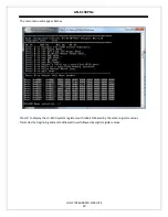
program outputs BC data blocks, BC instruction lists and HI-6130 system registers to the console after
each transmission. To view the transmissions on an oscilloscope, trigger rising edge on the ACTIVE test
point on the top left side of the card; put another scope probe on the ABBUS test point. Use a small clip
lead to bring this signal up to make it accessible to the scope probe. If no external RT or test equipment
is connected to the bus then use a 70 ohm termination resistor on the cable output or the signal will be
distorted when viewed with the oscilloscope.
Press”8” to command the BC to transmit three messages repeatedly to RT address = 3. Messages 1 and
3 are routed to the Bus A connector and message 2 is routed to the Bus B connector.
During transmissions LEDs 10 and 11 on the top edge of the card count in a binary fashion according to
the message sent. Two other LEDs flash when the HI-6130 is read or written by the program to provide a
visual aid during software development. LED 8 flashes when a read occurs and LED 9 flashes when a
write occurs.
Press “q” to quit.
This is the end of the Quick Start Guide section.


