


11
Intructions Additionnelles - Power Clamp – ZEEWB509AP03
Serrage / desserrage de roue
Blocage de l’arbre principal
Additional Instruction - Power Clamp – ZEEWB509AP03
Clamping / unclamping the wheel
Main shaft lock
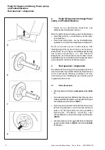
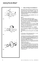
Par conséquent, la douille et le moyen de serrage sont
serrés contre la roue (
Fig. 10
).
•
Contrôler, avant la lancée de mesure, si la roue est
bien serrée.
Notes:
Si la pédale est actionnée encore une fois pendant le
serrage, le serrage est interrompu et les mors rentrent
en position desserrée. Le serrage peut être interrompu
également par actionnement de las touche STOP ou
ESC.
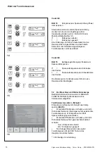
En cette équilibreuses l’image ENTREE DONNEES DE
ROUE se présente automatiquement après chaque
serrage.
Pour toutes les balco 9750P, la mesure est lancée
seulement si la roue est serrée et que le carter de roue
est fermé. Sinon, les codes d’erreur E14 (roue pas
serrée) ou E2 (carter de roue ouvert) sont lus.
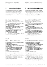
3.2
Desserrage de roue
Remarque
Pendant le desserrage des mors, retenir la roue pour
qu’elle ne tombe pas lors du desserrage.
•
Soulever la pédale (
Fig. 5
).
•
Prendre la douille de serrage du mandrin (
Fig. 11
).
•
Enlever la roue.
4.
Blocage de l’arbre principal
•
Appuyer sur la pédale pour bloquer l’arbre principal,
donc pour immobiliser ce dernier.
Par conséquent, la roue peut être retenue dans la position
de correction orientée afin de fixer les masses
d’équilibrage.
De plus, le serrage ou desserrage d’un écrou de serrage
de roue (du moyen de serrage SCA) est rendu plus
facile quand l’arbre principal est bloqué.
Dans les modes d’équilibrage Alu et seul pour les
masses d’équilibrage adhésives, le frein fonctionne
automatiquement comme ensemble combiné de frein
de positionnement et dispositif de blocage de l’arbre
principal dès qu’une pige de mesure a été enlevée de
sa position de repos et que la roue est orientée vers sa
position de correction relative.
Dans tous les modes d’équilibrage le frein fonctionne
comme frein de positionnement pour une orientation
plus aisée dans la position de correction relative.
As a result the clamping sleeve and the clamping means
are clamped against the wheel (
Fig. 10
).
•
Check for proper clamping prior to the measuring
run.
Notes
If the pedal is actuated once again during the clamping
process, clamping is interrupted and the clamping jaws
return to unclamped position. Clamping can also be
interrupted by operation of the STOP or the ESC key.
With the wheel balancers with screen balco 9750P the
screen RIM DATA INPUT comes up automatically after
every clamping operation.
With every balco P measurement can be started only
when the wheel is clamped and the wheel guard closed.
Otherwise error codes E14 (wheel not clamped) or E2
(wheel guard not closed) are read out.
3.2
Unclamping the wheel
Note
While the jaws unclamp, hold the wheel so that it
will not tilt when unclamped.
•
Lift the pedal (
Fig. 5
).
•
Remove the clamping sleeve from the chuck (
Fig.
11
).
•
Remove the wheel.
4.
Main shaft lock
•
Depress the pedal so as to actuate the main shaft
lock, thus locating the main shaft.
Consequently the wheel can be retained in the indexed
correction position to fit the balance weights.
Furthermore tightening or un-tightening of the wheel
clamping nut (of an SCA adaptor) is facilitated when
the main shaft is locked.
In the Alu balancing modes and for adhesive weights
only the brake works automatically as a combined
position brake and main shaft lock as soon as one of
the gauge arms has been removed out of its home
position and as the wheel is being indexed towards the
relative correction position.
In all the balancing modes the locking brake works as
a position brake for easier orientation towards the
correct correction position.


