

7
1.4.2-1
a
b
c
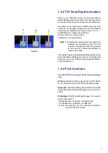
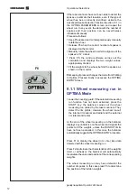
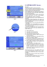
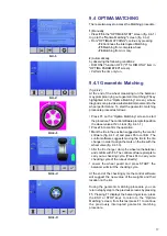
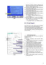
1.4.2 TDI Tread Depth Indication
When run in OPTIMA mode, the machine always
automatically detects the depth of the tread groove at
the centre of the tire and over its whole circumference.
According to the mean value detected and the limit
value set, the program displays one of the following
Tread Groove indications on screen (Fig. 1.4.2-1):
a) GREEN icon = higher than limit set.
b) YELLOW icon = close to limit.
c) RED icon = below limit set.
Note
: The information provided for the operator is
intended as a guideline only. The TDI
function is designed to alert the operator
to the need for a closer examination of
wear on the tread.
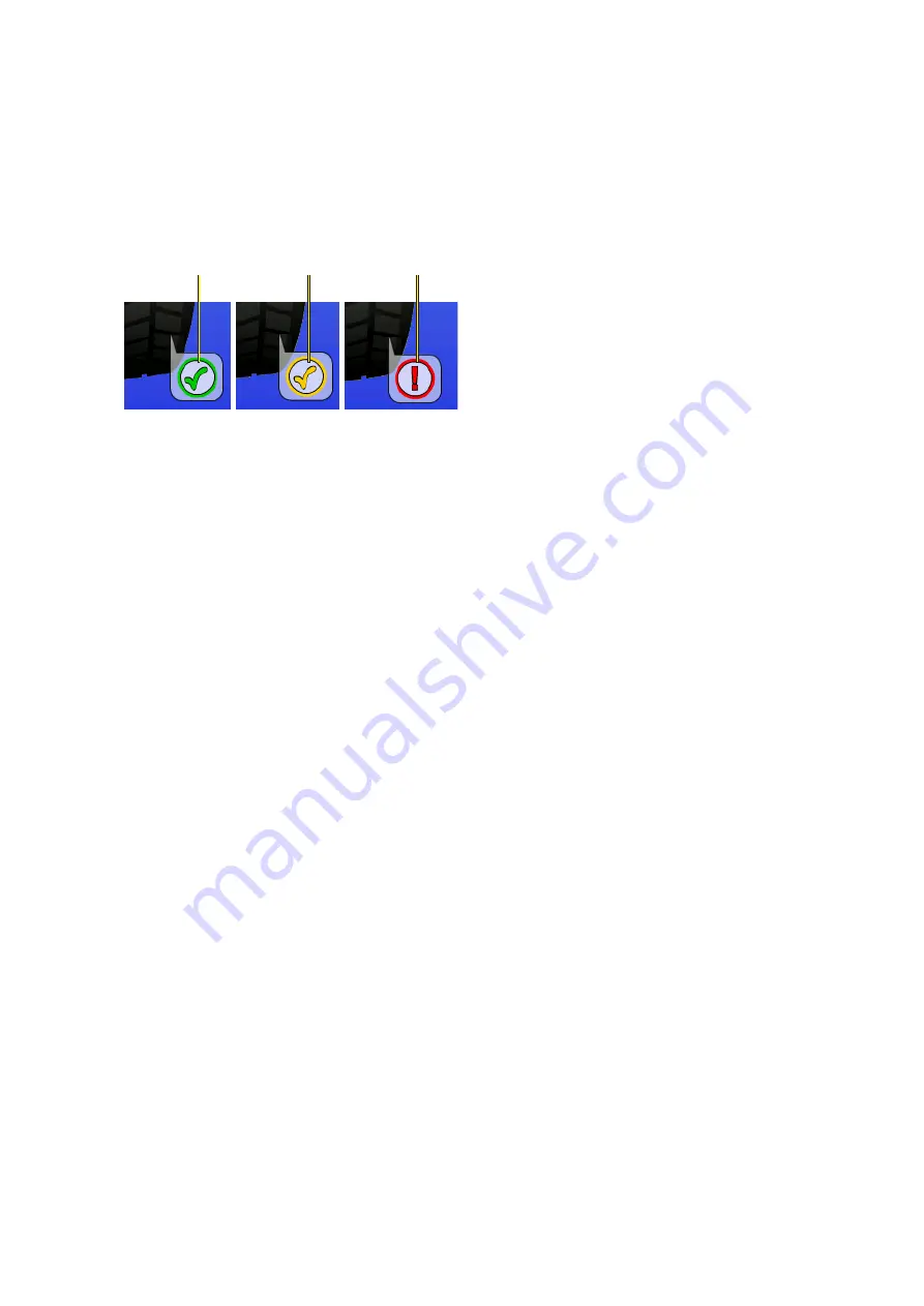
The operator can set the tread depth limit value for which
wear information will appear on screen. To change the
limit value go to the “Optima Operating Parameters”
menu (Section 9.7).
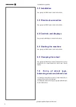
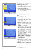
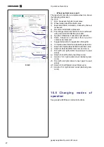
1.4.3 Print functions
The FUNCTION screen page includes three print settings
items:
Printing
. Field for switching the printer On/Off. Set to
On to enable printing. Set to Off to disable printing.
Paper size
. Field for selecting the print format. Activate
the format which matches the paper size used, A4 or
Letter
.
Printer type
. Field for selecting the type of connection
to the machine PC.
-
0
activates the connection via parallel port.
-
1
activates the connection via USB port.
-
2
sets the machine up for a special connection,
reserved for technicians.
Summary of Contents for geodyna optima
Page 1: ...geodyna optima Additional instructions Wheel balancer ...
Page 2: ......
Page 55: ...53 geodyna optima Operator s Manual Manuel d Utilisation Note Note page La página de la nota ...
Page 56: ...54 Electrical diagram ...
Page 57: ...55 Electrical diagram ...
Page 58: ...56 Electrical diagram ...
Page 59: ...57 Electrical diagram ...
Page 61: ...Note page ...


