

6
geodyna optima
Operator’s Manual
Safety & function
1.4-2
1.4-3
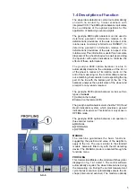
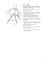
suggests the exact application point of the weight on
the rim through the laser beam (laser pointer).
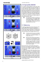
LASER POINTER:
even if inactive, the
Laser Pointer function is present on the
optima balancer. The machine is set in
geodata arm mode as default. The Laser
Pointer mode can be activated by
contacting service. For the use of the
geodata arm refer to the instructions
contained in the geodyna 6800 basic
manual.
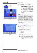
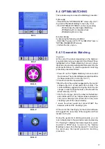
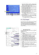
OPTIMA
Identifiable on the monitor with the symbol displayed
in fig. 1.4-2 detail 1. In this mode the balancer, as well
as the
profiling
, carries out the automatic diagnosis
of the
runout
and the reading for the TDI function.
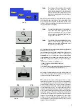
Control of the rim only:
in OPTIMA mode, clamping
only the rim on the balancer, the laser scanner detects
the absence of the tire. In this condition, the rear laser
analyses the
runout
on the bead recess in the internal
part of the rim and will prompt to automatically proceed
with the
matching
.
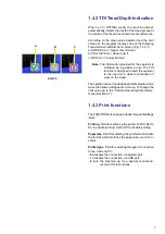
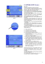
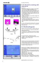
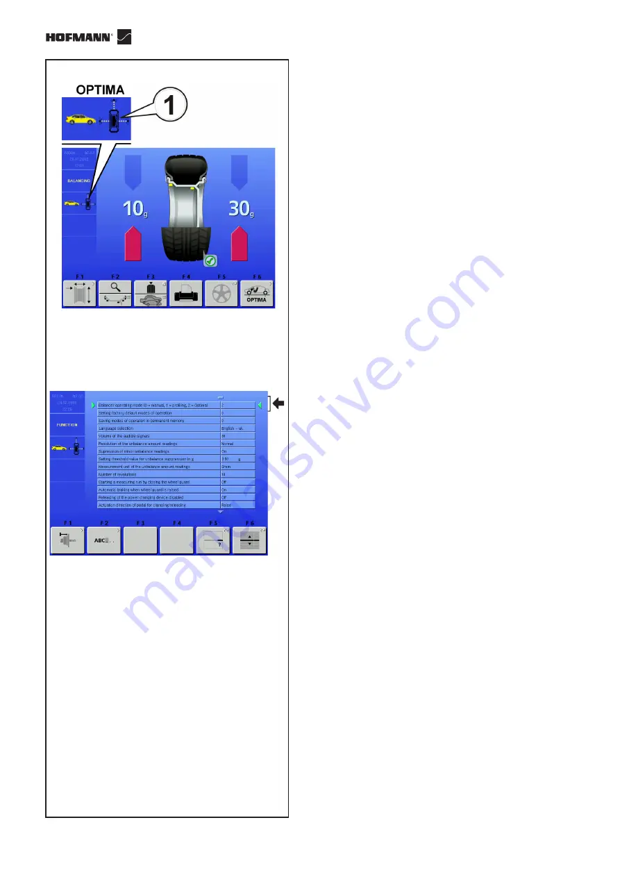
1.4.1 Switching operating modes
(fig. 1.4-3)
The balancer can be set so that it presents the desired
mode of operation at power-on.
•
Set the desired value in the functions menu:
0 - MANUAL;
1 - PROFILING;
2 - OPTIMA.
Keep the F6 key pressed to switch from Profiling to
Optima and vice versa.
Note:
refer to the geodyna 6800 basic manual
for the navigation procedure through the
function menus and personal data entry
modalities.
Summary of Contents for geodyna optima
Page 1: ...geodyna optima Additional instructions Wheel balancer ...
Page 2: ......
Page 55: ...53 geodyna optima Operator s Manual Manuel d Utilisation Note Note page La página de la nota ...
Page 56: ...54 Electrical diagram ...
Page 57: ...55 Electrical diagram ...
Page 58: ...56 Electrical diagram ...
Page 59: ...57 Electrical diagram ...
Page 61: ...Note page ...