


47
Operation manual geodyna 3000 / 3000m – 9412 178
Mode d’emploi geodyna 3000 / 3000m – 9412 178
Balancing the wheels
9.2
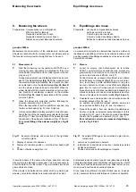
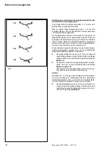
How to fit the balance weights correctly
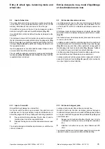
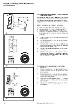
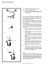
9.2.1 How to fit balance clips
•
Attach a balance clip in the relative correction position at
the rim flange exactly perpendicular to the main shaft
(Fig. 38).
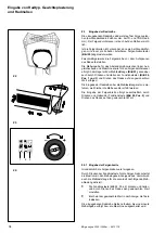
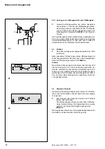
9.2.2 How to fit adhesive weights using the gauge head
After a measuring run in either of the Alu balancing modes the
gauge arm is set automatically to the position finding mode.
As soon as the gauge arm is removed from home position, the
left/right digital display shows the relative distance to the
correction plane. It is identical with the plane where the gauge
head was applied for data input.
As the gauge head approaches the correction plane, readings
go to zero. As the correction position is reached, a short audible
signal is given. If the gauge head goes beyond zero, a negative
sign appears before the distance reading.
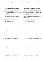
•
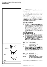
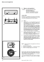
Index the wheel to correction position function of the
readings (Fig. 37) and retain using the main shaft lock.
•
Properly clean the fitting position before attaching the
adhesive weights.
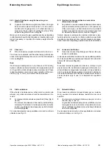
•
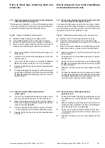
Centre and clamp an adhesive weight function of unbal-
ance readings (left or right correction plane) in the weight
holder of the gauge head and remove the cover film
(Fig. 39).
•
Approach the gauge head with the weight to the weight
fitting position until the left digital display shows zero and
an audible signal is given (Fig. 40 – e g Alu 2 mode, left
correction plane).
•
In this position apply the gauge head with the weight on
the rim and firmly press on the applicator to fit the weight
properly on the rim while at the same time removing the
gauge head to its initial position (Fig. 40).
•
Firmly press the adhesive weight once again on the rim.
•
Proceed analogously for the second (hidden) adhesive
weight until the right digital display shows zero and an
audible signal is given (Fig. 41 – e g Alu 2 mode, hidden
weight in right correction plane).
Note
If the error code E 20 is read out when the gauge arm is ap-
proached to the rim, there are no data for finding the correction
plane. This means that either an error was made in gauge arm
application, or the adhesive weight cannot be fitted on the rim
using the gauge head. In this case refer to the following chapter
How to fit adhesive weights based on given dimensions
Equilibrage des roues
9.2
Fixation correcte des masses d’équilibrage
9.2.1 Fixation des masses à ressort
•
Fixer une masses à ressort dans la position de correction
relative sur le rebord de jante, exactement perpendicu-
laire à l’arbre principal (Fig. 38).
9.2.2 Fixation des masses adhésives par la tête de pige
Après une lancée de mesure dans un des modes d’équilibrage
Alu, la pige est mise automatiquement au mode pour retrouver
la position de correction.
Dès que la pige est enlevée de sa position initiale, l’afficheur nu-
mérique gauche/droit montre la distance relative au plan de
correction. Celui est identique au plan où la tête de pige a été
appliquée pour l’entrée des données.
Les lectures tendent vers zéro au mesure où la tête de pige
s’approche du plan de correction. La position de correction at-
teinte, un bref signal sonore se fait entendre. Si la tête de pige
passe la position zéro, un signe négatif apparaît devant la lec-
ture.
•
Orienter la roue en position de correction fonction des
lectures (Fig. 37) et la tenir en place moyennant la pédale
de blocage.
•
Nettoyer la position de fixation sur la jante avant de ne
fixer les masses adhésives.
•
Centrer et serrer une masse adhésive fonction des lectu-
res du balourd (plan de correction gauche/droit) dans le
porte-masse de la tête de pige et enlever la feuille de pro-
tection (Fig. 39).
•
Approcher la tête de pige avec la masse de la position de
fixation jusqu’à ce que l’afficheur numérique gauche
montre zéro et qu’un signal sonore se fasse entendre
(Fig. 40 – par ex. mode Alu 2, plan de correction gau-
che).
•
Dans cette position, appliquer la tête de pige avec la
masse sur la jante et appuyer fermement sur l’applica-
teur pour bien fixer la masse sur la jante, tandis qu’en
même temps rentrant la tête de pige dans sa position ini-
tiale (Fig. 40).
•
Presser la masse adhésive encore une fois fermement
sur la jante.
•
Procéder par analogie pour la deuxième masse adhé-
sive (cachée) jusqu’à ce que l’afficheur numérique droit
montre zéro et qu’un signal sonore se fasse entendre
(Fig. 41 – par ex. mode Alu 2, masse cachée dans le
plan de correction droit).
Note
Si le code d’erreur E 20 est lu quand la pige est approchée de la
jante, il n’y a pas de données pour retrouver le plan de correc-
tion. Donc une erreur a été faite en appliquant la pige, ou la
masse adhésive ne peut pas être fixée moyennant la tête de
pige. Dans ce cas, voir le chapitre suivant Fixation des mas-
ses adhésives suivant des dimensions données.