8
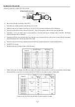
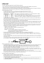
4.2 Wiring and terminal description
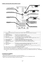
Note 1) Above shows an example of voltage (O) input. Changeover of SW6 must be done in case of current (OI) input. (Refer to page 9).
(1) Mains terminal description
Symbol
Name
Description
R/L1(L1)
Power input terminals
Connect power supply
- Use [L1] and [N] terminal in case of 1-ph. 200V power supply
S/L2
T/L3(N)
U/T1
Power output terminals
Connect 3-ph. motor
V/T2
W/T3
PD/+1
DC link choke connection
terminal
First, remove the short circuit bar between PD/+1 and P/+ terminal.
Then connect optional DC link choke for improving the input harmonics.
P/+
G( )
Earth terminal
To make grounding. Be sure to make this grounding to avoid electric shock, and for improving
the EMC performance. The terminal is located on the heatsink.
Intelligent inputs,
7 terminals
0-10VDC(10bit)
PLC
P24
DC24V
L
P/+
H
O/OI
Category D grounding (200V class)
DC10V
5
2
1
3
4
Intelligent input terminal
11
CM2
Relay contacts
AL0
AL1
AL2
L
DC10V
(10mA Max.)
4.7k
Ω
4.7k
Ω
L
FM
L
Pulse train output
L
L
PD/+1
Refer to QRG (section 5.7) when using
external equipment for source logic
output and/or external power supply.
Short circuit bar
Short circuit bar
DCL
Remove the jumper
wire when using DCL
(DC link choke)
ELB
1k
Ω
~
2k
Ω
(L1)
(
N
N
N
N
)
Approx.
250
Ω
O
O
O
O
OI
SW6
Motor
U/T1
V/T2
W/T3
M
Power source,
3-phase or
1-phase, per
inverter model
R/L1
S/L2
T/L3
MC
Approx.1
0k
Ω

