11
④
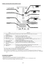
Inverter ground terminal (G )
・
Be sure to ground the inverter and motor to prevent electric shock.
・
According to the Electric Apparatus Engineering Regulations, connect 200 V class models to grounding electrodes constructed in compliance
with type-D grounding (conventional type-III grounding with ground resistance of 100
Ω
or less) or the 400 V class models to grounding electrodes
constructed in compliance with type-C grounding (conventional special type-III grounding with ground resistance of 10
Ω
or less).
・
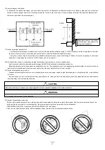
Use a grounding cable thicker than the specified applicable cable, and make the ground wiring as short as possible.
・
When grounding multiple inverters, avoid a multi-drop connection of the grounding route and formation of a ground loop, otherwise the inverter
may malfunction.
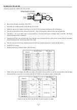
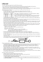
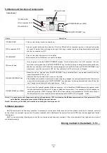
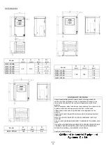
(2) Layout of main circuit terminals
The figures below show the terminal layout on the main circuit terminal block of the inverter.
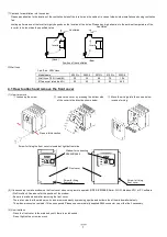
The main circuit terminal block opens a faceplate and wires it.
Single-phase 200V 0.2 to 0.4kW
Three-phase 200V 0.2 to 0.75kW
(4)Wiring and Accesories
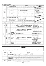
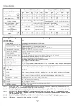
The table below lists the specifications of cables, crimp terminals, and terminal screw tightening torques for reference.
Input
Voltage
Motor
output
(kW)
Applicable
inverter
model
NES1-
Wiring
Accessories
Note1)
Gauge of power line
cable (mm
2
)
Note3)
Note4)
Size of terminal
screw
Terminal width
(mm)
Tightening
torque
(N-m)
Earth-leakage
breaker (ELB)
Note2)Note5)
Magnetic
contactor
(MC)
Note2)
Fuse
(UL-rated,
class J,600V)
Note6)
1-phase
200V
0.2
002SB
AWG14 (2.0)
M3.5 (7.6)
1.0
EX30 (5A)
H10C
10A
0.4
004SB
AWG14 (2.0)
M3.5 (7.6)
1.0
EX30 (10A)
H10C
10A
0.75
007SB
AWG14 (2.0)
M4 (10)
1.4
EX30 (15A)
H10C
15A
1.5
015SB
AWG10 (5.5)
M4 (10)
1.4
EX30 (20A)
H20
20A
2.2
022SB
AWG10 (5.5)
M4 (10)
1.4
EX30 (20A)
H20
30A
3-phase
200V
0.2
002LB
AWG16 (1.25)
M3.5 (7.6)
1.0
EX30 (5A)
H10C
10A
0.4
004LB
AWG16 (1.25)
M3.5 (7.6)
1.0
EX30 (10A)
H10C
10A
0.75
007LB
AWG16 (1.25)
M3.5 (7.6)
1.0
EX30 (10A)
H10C
15A
1.5
015LB
AWG14 (2.0)
M4 (10)
1.4
EX30 (15A)
H10C
15A
2.2
022LB
AWG14 (2.0)
M4 (10)
1.4
EX30 (20A)
H20
20A
Note 1)The peripheral equipment described here is applicable when the inverter connects a standard Hitachi 3-phase, 4-pole squirrel-cage motor.
Note 2)Select breakers that have proper capacity. (Use breakers that comply with inverters.)
Select above proper ELB capacity following above table
for the 1pc inverter. Only 1 inverter must be supplied by the above proper ELB.
Note 3)If the power line exceeds 20m, cable that is thicker than the specified applicable cable must be used for the power line.
Note 4)Use copper electric wire (HIV cable) of which the maximum allowable temperature of the insulation is 75°C.
Note 5)Use earth-leakage breakers (ELB) to ensure safety.
Note 6)To comply UL, use either ELB/or FUSE which is specified by UL for the Power supply for the inverter.
Note 7)The ground or earthed line should be a larger gauge than electric supply wire diameter used in the power line.
Three-phase type
Single-phase
type
Three-phase
type
From source
To motor
L1
N
P/+
PD/+1
W/T3
V/T2
U/T1
R/L1
T/L3
P/+
PD/+1
W/T3
V/T2
U/T1
S/L2
Single-phase type
L1
N
PD/+1
P/+
U/T1
W/T3
V/T2
R/L1
T/L3
S/L2
W/T3
V/T2
U/T1
PD/+1
P/+
From source
To motor
Single-phase 200V 0.75 to 2.2kW
Three-phase 200V 1.5, 2.2kW
Charge lump
Charge lump
Inverter
Inverter
Inverter
Grounding bolt
prepared by user
Inverter
Inverter
Inverter

