background image

Revision A      June 27, 2011 

20 / 49 


Item 

C (R. No) 

D1 

D2 

D3 

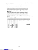
SENS UP mode 

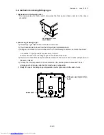
OFF 

(*)

 1A 

00 

00 

00 

AUTO x 2 

1A 

01 

00 

00 

AUTO x 4 

1A 

02 

00 

00 

AUTO x 6 

1A 

03 

00 

00 

AUTO x 8 

1A 

04 

00 

00 

AUTO x10 

1A 

05 

00 

00 

AUTO x12 

1A 

06 

00 

00 

AUTO x16 

1A 

07 

00 

00 

AUTO x32 

1A 

08 

00 

00 

AUTO x64 

1A 

09 

00 

00 

AUTO x128 

1A 

0A 

00 

00 

OFF 1A 

0B 

00 

00 

MANU x 2 

1A 

0C 

00 

00 

MANU x 4 

1A 

0D 

00 

00 

MANU x 6 

1A 

0E 

00 

00 

MANU x 8 

1A 

0F 

00 

00 

MANU x10 

1A 

10 

00 

00 

MANU x12 

1A 

11 

00 

00 

MANU x16 

1A 

12 

00 

00 

MANU x32 

1A 

13 

00 

00 

MANU x64 

1A 

14 

00 

00 

MANU x128 

1A 

15 

00 

00 

MANU x192 

1A 

16 

00 

00 

MANU x256 

1A 

17 

00 

00 

MANU x320 

1A 

18 

00 

00 

MANU x384 

1A 

19 

00 

00 

MANU x448 

1A 

1A 

00 

00 

MANU x512 

1A 

1B 

00 

00 

Notes: It compulsorily becomes 1/60 if it transmits excluding SENS UP turning off when setting it 
excluding SHUTTER SPEED: 1/60 and 1/100. 
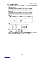
White Balance Mode 

ATW 

(*)

 04 

00 

00 

00 

AWC 04 

01 

00 

00 

MANUAL 04 

02 

00 

00 

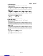
ATW RANGE 

NORMAL 

(*)

 62 

00 

00 

00 

SPECIAL 62 

01 

00 

00 

          (*)

: Factory setting 

Summary of Contents for KP-D5010-S1

Page 1: ...amera KP D5010 S1 Operation manual Thank you for purchase this fine Hitachi Kokusai Electric color CCD housing camera Before using the camera please read this operation manual carefully and keep this manual on file for ready reference in the future ...

Page 2: ...k stops excessive force and uneven surfaces may cause the product and cart combination to overturn 10 Ventilation Slots and openings in the cabinet are provided for ventilation and to ensure reliable operation of the product and to protect it from overheating and these openings must not be blocked or covered The openings should never be blocked by placing the product on a bed sofa rug or other sim...

Page 3: ...o qualified service personnel under the following conditions a When the power supply cord or plug is damaged b If liquid has been spilled or objects have fallen into the product c If the product has been exposed to rain or water d If the product does not operate normally by following the operating instructions Adjust only those controls that are covered by the operating instructions as an improper...

Page 4: ... Operating considerations Notes to users 5 3 CCD characteristics 5 4 Name and function of each section 6 5 Connection 8 6 A method of enclosing Nitrogen gas 9 7 Remote control protocol command 10 8 Setting Camera Menu description 24 9 Main specifications 46 ...

Page 5: ... the camera is used continuously for long time under high ambient temperature the inside electrical parts become deteriorated resulting in shortening its life To use the camera continuously for long time the highest temperature must be below 60 5 Cleaning a Use a blower or a lens brush to remove dusts on the lens or the front glass b Wipe dirt on the case off with dry soft cloth If dirt is hardene...

Page 6: ...er of CCD image sensor might be deteriorated and the color of the corresponding portion may change Do not set or keep lens or CCD towards sun or extremely strong light direction in either power on or off state 5 White spot Imperceptible white spots may rarely come up on the screen due to cosmic rays and so on It becomes easy to appear when the sensitivity of the camera is raised in the operation a...

Page 7: ... implantation bulb Refer to page 9 A method of enclosing Nitrogen gas Relief bulb Refer to page 9 A method of enclosing Nitrogen gas Video output BNC connector REMOTE Power supply connector Refer to page 8 Bottom view Camera installation screw 4 1 4 20UNC Corresponds to M Install these screws to the bottom of the camera ...

Page 8: ...al data output G N C Do not connect H N C Do not connect J N C Do not connect K N C Do not connect L Tx Rx GND Serial data ground M N C Do not connect N N C Do not connect P N C Do not connect R N C Do not connect S N C Do not connect T N C Do not connect U N C Do not connect V N C Do not connect W N C Do not connect X N C Do not connect Y N C Do not connect Z N C Do not connect a N C Do not conne...

Page 9: ...on the following conditions and air in the case is Conditions 7 2 psi pound per square inch 10L min This has aimed to raise the nitrogen gas concentration in the case d The air vomit hole of the front panel will be closed with the screw in five minutes and pressure in the case is raised e To keep the internal pressure to be constant when the internal pressure exceeds 7 25 psi nitrogen gas that is ...

Page 10: ...transmits the reply command to the actuator Notes The housing camera disregards the transmission command received from the reception of the command to the transmission of the reply command Figure 1 Communication protocol Actuate Housing camera The command is transmitted Command transmission The command is received Is the destination address the same as camera ID and is the checksum same The reply ...

Page 11: ...sion command transmitted from actuator The destination address and the source address of the transmission command are replaced and the reply command is transmitted Reply command format Notes As for data 1 3 of the reply command the same data as the transmission command is sent back However data is buried when there is reading information by the transmission command The housing camera transmits the...

Page 12: ...disregarded Notes When the one shown in the following was a busy the transmission command was transmitted 1 Initial busy 2 Lens busy 3 When camera menu opens Please end the operation shown below or transmit the transmission command after operation ends Initial busy Initial busy The camera is being initialized It waits until initial operation ends Camera unit failure At the state of the camera unit...

Page 13: ... parameter vv and ww operates by 1 Present operation is assumed to be continuance for 1 of both of bits that direct a different direction and it stops for both 0 Command 1 Command 2 Data 1 Data 2 Data 3 Data 4 vv ww xx yy zz FFh Command 1 Command 2 Data 1 Data 2 Data 3 Data 4 vv ww xx yy zz error Bits vv ww xx yy zz 7 0 Fixed 0 Fixed FFh Fixed FFh Fixed Focus speed 01h 08h 6 0 Fixed Wide 5 0 Fixed...

Page 14: ...meters d 40h End FFFFh After the end is acquired the presetting movement is done The working area is as shown in the following Zoom 0 255 WIDE TELE FOCUS 0 255 FAR NEAR The value of the WIDE edge and the TELE edge of optical system is different in each camera Please confirm the value of the edge by Call Current Position command M Content YH YL Content 02h Zoom 0000h 00FFh 03h Focus 0000h 00FFh 80h...

Page 15: ...command Parameter M Content YH YL Content 02h Zoom 0000h 00FFh 03h Focus 0000h 00FFh Command 1 Command 2 Data 1 Data 2 Data 3 Data 4 00h 87h M FFh FFh FFh Command 1 Command 2 Data 1 Data 2 Data 3 Data 4 00h 87h M YH YL error Command 1 Command 2 Data 1 Data 2 Data 3 Data 4 00h 7Dh P FFh FFh FFh Command 1 Command 2 Data 1 Data 2 Data 3 Data 4 00h 7Dh P FFh FFh error P Content 00h Camera menu open sw...

Page 16: ...s of extender function Transmission command Reply command Parameter Command 1 Command 2 Data 1 Data 2 Data 3 Data 4 00h 61h S FFh FFh FFh Command 1 Command 2 Data 1 Data 2 Data 3 Data 4 00h 61h S FFh FFh error S Content 00h Extender OFF 01h Extender ON Command 1 Command 2 Data 1 Data 2 Data 3 Data 4 00h FDh S FFh FFh FFh Command 1 Command 2 Data 1 Data 2 Data 3 Data 4 00h FDh S FFh FFh error S Con...

Page 17: ... is a command to acquire the state of the camera Transmission command Reply command Parameter C Relativity Number R No D1 Data 1 D2 Data 2 D3 Data 3 Please refer to Camera Command List on page 18 for details Command 1 Command 2 Data 1 Data 2 Data 3 Data 4 00h DBh C D1 D2 D3 Command 1 Command 2 Data 1 Data 2 Data 3 Data 4 00h DBh C D1 D2 D3 Command 1 Command 2 Data 1 Data 2 Data 3 Data 4 00h DDh C ...

Page 18: ...TROL PEAK AVE 0 100 39 00 00 00 15 85 39 01 00 00 30 70 39 02 00 00 50 50 39 03 00 00 75 25 39 04 00 00 100 0 39 05 00 00 Video Level LEVEL 00 FF Min 0C 00 00 00 0C 00 00 Mid 0C 80 00 00 0C 00 00 Max 0C FF 00 00 AIE mode OFF 63 00 00 00 LOW 63 01 00 00 MID 63 02 00 00 HIGH 63 03 00 00 AGC mode OFF 06 01 00 00 ON 06 00 00 00 Notes If the AGC setting is switched to turning off when B W mode sets AUT...

Page 19: ...LENS 08 0E 00 00 Notes 1 When SENS UP AUTOx is set only 1 60 1 100 can be set When other transmitting if compulsorily becomes 1 60 2 When SENS UP MANUx is set it becomes 1 60 fixation B W mode OFF 64 00 00 00 ON 64 01 00 00 AUTO HI 64 02 00 00 AUTO MID 64 03 00 00 AUTO LOW 64 04 00 00 Notes When AGC OFF is set only turning off or turning on can be set BURST OFF 9B 00 00 00 ON 9B 01 00 00 Digital z...

Page 20: ...A 0E 00 00 MANU x 8 1A 0F 00 00 MANU x10 1A 10 00 00 MANU x12 1A 11 00 00 MANU x16 1A 12 00 00 MANU x32 1A 13 00 00 MANU x64 1A 14 00 00 MANU x128 1A 15 00 00 MANU x192 1A 16 00 00 MANU x256 1A 17 00 00 MANU x320 1A 18 00 00 MANU x384 1A 19 00 00 MANU x448 1A 1A 00 00 MANU x512 1A 1B 00 00 Notes It compulsorily becomes 1 60 if it transmits excluding SENS UP turning off when setting it excluding SH...

Page 21: ...is command is transmitted at AWC the white balance is taken heart R GAIN OFFSET for AWC 00 FF Min 46 00 00 00 46 00 00 Mid 46 80 00 00 46 00 00 Max 46 FF 00 00 B GAIN OFFSET for AWC 00 FF Min 47 00 00 00 47 00 00 Mid 47 80 00 00 47 00 00 Max 47 FF 00 00 R GAIN for MANUAL 00 FF Min 0D 00 00 00 0D 00 00 Mid 0D 80 00 00 0D 00 00 Max 0D FF 00 00 B GAIN for MANUAL 00 FF Min 0E 00 00 00 0E 00 00 Mid 0E ...

Page 22: ...00 Max 16 B2 00 00 DETAIL 00 FF Min 15 00 00 00 15 00 00 Mid 15 80 00 00 15 00 00 Max 15 FF 00 00 FOG Correction OFF 18 00 00 00 AUTO 18 01 00 00 MANUAL 18 02 00 00 Scene file switch File1 A8 00 00 00 File2 A8 01 00 00 File3 A8 02 00 00 File4 A8 03 00 00 File5 A8 04 00 00 CAMERA RESET 4F 00 00 00 Factory setting ...

Page 23: ...R SPEED 08 00 00 00 B W MODE 64 00 00 00 BURST 9B 00 00 00 Digital zoom 37 00 00 00 LENS type select A9 00 00 00 Polarity 01 00 00 00 MIRROR A3 00 00 00 SENS UP 1A 00 00 00 White balance mode 04 00 00 00 ATW RANGE 62 00 00 00 WB AREA 3B 00 00 00 WB area no 3C 00 00 00 R GAIN OFFSET for AWC 00 FF 46 00 00 00 B GAIN OFFSET for AWC 00 FF 47 00 00 00 R GAIN for MANUAL 00 FF 0D 00 00 00 B GAIN for MANU...

Page 24: ... BLC on off and area setting Video level adjustment AGC setting page13 Shutter speed setting page 15 Sensitivity enhancement setting page 16 Color B W selection page 17 AGC mode setting White balance setting page 18 Scene file setting page 9 Light control menu page10 Camera title setting page 22 Main menu page 9 Sub menu page 28 Lens setting etc Bursts setting Command 1 Command 2 Data 1 Data 2 Dat...

Page 25: ...ry setting is FILE1 Scene file factory setting Scene file No 1 2 3 4 5 High sensitivity setting Fog adjustment color setting Fog adjustment B W setting Back light correction setting Stored high sensitivity setting LIGHT CONTROL MODE AVERAGE AVERAGE AVERAGE BLC AVERAGE AREA NO 1 AIE OFF OFF OFF MID OFF AGC 51 31 31 31 51 SENS UP OFF OFF OFF OFF AUTOx16 B W MODE OFF OFF ON OFF OFF FOG ADJUST OFF AUT...

Page 26: ...rage mode This mode uses the peak luminance together with average and controls the exposure level The ratio of peak level and average level can be changed 2 Video level adjustment The optimum video level is to factory setting 000 If necessary the level can be changed as foIIows a Use UP or Down commands to move the cursor to LEVEL b The adjusted value changes into the blinking if the SET command i...

Page 27: ...trong light or sun light is hitting the spot besides the place to be observed and the subject of interest becomes dark This mode is used to avoid darkening of subject of interest in such condition a Use UP or Down commands to move the cursor to MODE b It cuts in the following menu display when the SET command is transmitted and BLC is set and it changes c When the cursor is matched to AREA SELECT ...

Page 28: ...spot within the image the near by area of spot may have overexposure and the subject might not be confirmed This mode is used when taking picture under such condition It can control overexposure in such conditions a Use UP or Down commands to move the cursor to MODE b It cuts in the following menu display when the SET command is transmitted and PEAK AVE is set and it changes c The ratio of peak av...

Page 29: ...ondition when the SET command is transmitted AGC MENU is displayed d When the SET command is transmitted the AGC mode is changed Set command ON OFF ON Automatically changes the video level within a range of the AGC limit as appropriate according to the brightness of subject AGC is set to ON in factory setting OFF Always sets a fixed video level from the FIX GAIN 2 AGC limit setting AGC ON a Use UP...

Page 30: ...t value is fixed The blinking display ends and the cursor moves to DNR Note At high AGC LIMIT FIX GAIN sensitivity increases but noise becomes more apparent 4 Digital Noise Reduction DNR setting It is a function to reduce the noise element generated by AGC gain increment a Use UP or Down commands to move the cursor to DNR b It changes if the cursor is matched to DNR by the SET command is transmitt...

Page 31: ...electronic shutter speed according to the amount of incident light and keep the image level constant Note a When using a DC type VIDEO type auto iris lens fix the iris to fully open b When the following phenomenon occurs while AES is operating change to different shutter speed The following are not defects Strong smear or blooming occurs in the scene Screen flicker or coloration occurs Main menu M...

Page 32: ...ting 1 60 1 50 Relation of SENS UP setting and SHUTTER SPEED SENS UP Setting OFF AUTO MANU SHUTTER SPEED 1 60 1 50 1 60 1 50 1 60 1 50 1 60 1 50 1 100 1 120 1 100 1 120 1 100 1 120 1 60 1 50 1 250 1 100000 1 250 1 100000 1 60 1 50 1 60 1 50 AES AES AES 1 60 1 50 a SHUTTER SPEED can not be changed to be other than 1 60 or 1 100 when SENS UP is AUTO and MANU b If SHUTTER SPEED setting is other than ...

Page 33: ...f the SET command is transmitted B W MODE MENU is displayed d Use the Up and Down buttons to move the cursor to MODE e In this state push the SET command to change the shutter speed as follows Set command OFF ON AUTO H AUTO M AUTO L OFF This mode is of color picture factory setting ON This mode is of black and white picture AUTO In this mode color image black and white image is changed automatical...

Page 34: ...ment value range 001 030 unit second Factory setting is 005 Color BW switching The camera CCD responds to infrared light 700 1000nm that is invisible to the human eye Normal color camera uses an IR cut filter to remove the infrared components in order to bring it close to human eye This condition is used for color image In case of black and white image the IR cut filter is removed in order to maki...

Page 35: ...acking white balance mode This mode automatically adjusts white balance according to the color temperature of the subject Generally this mode is used AWC Preset White Balance mode This mode automatically adjusts the white balance Color temperature range for AWC is 2300K 10000K MANUAL Manual white balance mode This mode adjusts the white balance by manually adjusting R B gain It is used when white ...

Page 36: ... to WB AREA by the UP or DOWN command b The SET command is transmitted and the white detection area mode is switched Please set it according to use conditions SET command OFF ON NO 1 9 OFF White detection from whole screen ON NO White detection from specified area c When the display becomes turning on NO AREA SELECT is displayed below by one line d When the cursor is matched to AREA SELECT and the...

Page 37: ...er completion of automatic adjustment it is possible to adjust white balance precisely by adjusting R B gain a The cursor is moved to R GAIN OFFSET or B GAIN OFFSET by the UP or DOWN command and the SET command is transmitted Then a right adjusted value blinks b Under such a condition the adjusted value changes if the UP or DOWN command is transmitted and the white balance can be fine tuned Adjust...

Page 38: ...s transmitted and the white balance can be adjusted Adjustment value range 128 000 127 h It returns to initialization 000 when the UP DOWN command is transmitted Blinking stops if the SET command is transmitted with the cursor has blinked and a set value is fixed Main menu MAIN MENU FILE1 LIGHT CONTROL AVE AGC ON SHUTTER SPEED 1 60 SENS UP OFF B W MODE OFF WHITE BALANCE ATW CAMERA TITLE OFF ENHANC...

Page 39: ...camera title b The blinking cursor moves to the line of ALPHA or the Japanese syllabary and the kanji character when the DOWN command is transmitted The katakana is displayed in the alphanumeric character the sign and the Japanese syllabary display when the display is ALPHA and the kanji character is displayed in the input character selection part in the kanji character display c The cursor change...

Page 40: ...and is transmitted it is 1 revocable RESET When all characters displayed in the camera title character display part are erased it uses it The blinking cursor is matched to RESET and the SET command is transmitted All characters are erased and the blinking cursor returns to the first position of the camera title character display part afterwards RET When the camera title CHARACTER SETTING MENU is e...

Page 41: ... when color level is increased too much In case of black and white picture mode of BW MODE the CHROMA level can not be fixed to 128 2 Detail setting DETAIL a It is set to the best amount of an outline correction when shipping it and a right set value blinks to change when the cursor is moved to DETAIL by the UP or DOWN command and the SET command is transmitted Adjustment value range 128 000 128 b...

Page 42: ... Adjustment value range 128 000 127 b It returns to initialization 000 when the UP DOWN command is transmitted Blinking stops if the SET command is transmitted with the numerical value has blinked and a set value is fixed 5 Gamma correction setting GAMMA Use the Up or Down command to move the cursor to GAMMA Under such a condition the gamma setting cuts when the SET command is transmitted and it c...

Page 43: ... is high when mist is subjected to the whole screen and effect is low when mist is subjected to a part of the subject Fog adjustment is done automatically Note a When uniform subject is being captured correction is done even if there is no mist b There might be noise with this function depending on the picture shooting conditions c Block noise might be seen due to automatic processing of this func...

Page 44: ...m is set to OFF Sub menu SUB MENU a The OPEN command is transmitted and MAIN MENU is opened b When the cursor is matched to SUB MENU by the UP or DOWN command and the SET command is transmitted SUB MENU is displayed 1 Lens Type setting LENS TYPE a The LENS TYPE display blinks when the cursor is matched to LENS TYPE by the UP or DOWN command Under such a condition when the SET command is transmitte...

Page 45: ... SET command is transmitted and it changes Set command OFF ON Lens Open 3 Return to camera factory setting CAMERA RESET It returns to the state when various settings of the camera ship all factories when the cursor is matched to CAM RESET and the UP DOWN command is transmitted It returns to the MAIN MENU after it ends Please see the explanation of each item in the factory default setting of each s...

Page 46: ...ion 0 003 lx at integrated mode 128 times B W 0 05 lx Tungsten lamp 0 0004 lx at integrated mode 128 times 3 Lens Zoom 55 times Pentax H55ZAME 5F Focal distance f 12 660 wo extender f 30 5 1680 w extender 2 5x Angle of view Horizontal 31 6 0 6 wo extender 12 1 0 2 w extender 2 5 xs Vertical 23 2 0 4 wo extender 9 0 0 2 w extender 2 5x 4 Camera housing I F on the multi connector MIL C 26482 Ⅰ type ...

Page 47: ...7 49 8 Protecting structure IP67 Applied to IEC EN60529 9 Dimensions Approx 227 W 198 H 700 D mm 10 Mass Approx 19kg Housing lens Camera Option excluded or less 11 Painting Color 33446 Desert Tan Color By FEDERAL STANDARD 595C ...

Page 48: ...Revision A June 27 2011 48 49 ...

Page 49: ... 345 5379 South Sales Service 1 256 774 3777 Parts Center Phone 1 516 682 4435 Fax 1 516 921 0993 Latin Sales Phone 1 519 682 4420 Fax 1 516 496 3718 URL http www hitachikokusai us Hitachi Kokusai Electric Canada Ltd Head Office 1 Select Avenue Unit 12 Scarborough Ontario M1V 5J3 Canada Phone 1 416 299 5900 Fax 1 416 299 0450 Eastern Office 5795 Chemin St Francois St Laurent Quebec H4S 1B6 Canada ...

Reviews: