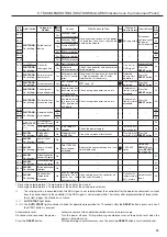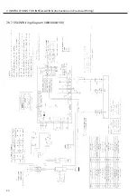
Control air flow
Operation
Mode
20US
20P
Action of
suction
throttle valve
55kW
75kW
Starting
NO
−
COM
NO
−
COM
Opened
Fully closed
Loading
NC
−
COM
NC
−
COM
Closed
Fully opened
Unloading
NO
−
COM
NO
−
COM
Opened
Fully closed
Stopping
NO
−
COM
NO
−
COM
Opened
Fully closed
Pressure
sensor
PS
COM
NO
NC
20US
COM
NC
NO
20P
55kW
Only 75kW
20P
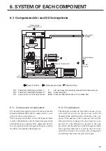
Suction Throttle Valve
Aftercooler
From air
intake filter
Orifice
To the
air end
To the discharging
air pipe
Orifice
20P
:
Blowoff solenoid valve
20US
:
Control solenoid valve
PS
:
Pressure sensor (1)
Oil Separator
To the air end
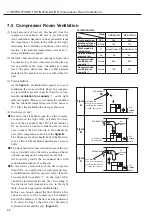
6.2 Capacity Control System
See page 15 for changing the pressure settings and the
capacity control mode respectively.
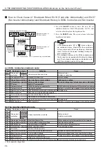
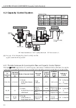
6.2.1 Relation between Air Consumption Rate and Capacity Control System
The Vplus
HISCREW
supports three (V, I, and P) capacity control modes. As illustrated in the table below, the capacity
control system automatically activates the most desirable mode depending on the air consumption of your plant airline.
Compressed
Air
Consumption
(%)
Operating
Frequency
(
Hz
)
Mode of Capacity Control
Pressures
to Set
Factory
Settings
(MPa)
Allowable
Setting
Range
(MPa)
Settings of
F mode
30 to 105
40 to 142
①
V-mode:
CPCS Motor Speed
Control
Target
pressure
0.7
0.45 to 0.85
F011
…
0 (Disable)
or
F011
…
1 (Enable)
3 to 30
40
②
I
-mode:
Online/Offline Control
with Blowoff
Cutout
pressure
0.78
Target pr
(0.02 to 0.08) F011
…
0 (Disable)
or
F011
…
1 (Enable)
Cutin
pressure
0.7
Target pressure
0 to 3
Motor
OFF
③
P-mode:
Automatic Motor
Stop/ Restart Control
Motor restart
pressure
0.6
0.45 to
Target pressure
F011
…
0 (Disable)
30
6. SYSTEM OF EACH COMPONENT [Capacity Control System]

