background image

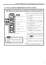
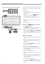
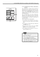
(1)  For safety, the machine cannot be operated for 5 sec-

onds after turning the power on even if the 

START

 but-

ton is pressed.  If the 

START

 button is pressed within 

the period between 5 and 15 seconds after the power-
on, the 

STANDBY

 light blinks for up to 10 seconds for 

preparation and then the compressor is started. 

(2) Be sure to close the covers before operating.
(3)  Every button such as 

START

STOP

 and 

RESET

 will 

not function unless the button hold down more than 
0.3 second.

For safety, the machine cannot be operated for 5 seconds 
after turning the power on even if the 

START

 button is 

pressed. If the 

START

 button is pressed within the period 

between 5 and 15 seconds after the power-on, the 

STANDBY

 light blinks for up to 10 seconds for prepara-

tion and then the compressor is started. 

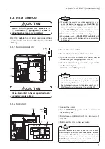
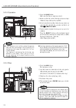
 Be sure the power is OFF.


Be sure that grounding is firmly connected.

 Open the front door and make sure the oil separator 

tank internal pressure gauge reads 0 MPa.

 Check if oil level is kept around the upper red line 

on the oil level gauge.

     (Oil level lowers while operation)

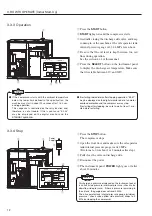
Connect the power.

 See  if 

POWER

 light glows on the compressor’s 

instrument panel.

 Digital monitor displays discharge air pressure by 

0.01MPa.

Fully open the valve on discharge side.

IMPORTANT

IMPORTANT

Power 
Supply

Power 
Supply

RUNNING CONTROL

RUNNING MODE

ALARM

警 报

运行状况

故 障

LOAD

SHUTDOWN

REMOTE

负 载

远 程

电 源

POWER

自动启动

AUTO START

停 机

STOP

开 机

START

存 储

远 程

REMOTE

显示转换/

扩展模式

STR

功 能

FUNC

重新设定

RESET

SELECT/WIDE

运行管理

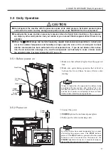
After the installation, or after long unused time 
(over a week), run the machine by way of initial 
start-up.

・ 

Hitachi presets the capacity control mode to “A” or 
enables the P-mode. Refer to page 15 for changing it to 
“U” or disabling the P-mode.

・ 

The discharge air pressure of standard specification is 0.7 
MPa. The motor restart pressure of P-mode is 0.6 MPa

IMPORTANT

3.3  Initial Start-Up

 CAUTION

Before turn the power ON, make sure if 

 installation, 

 piping and 

 electrical 

wiring have been properly completed.

3.3.1  Before power on

3.3.2  Power on

 CAUTION

Oil has been filled in the oil separator tank by 
the factory before delivery.

11

3. HOW TO OPERATE [Initial Start-Up]

Summary of Contents for HISCREW V PLUS NEXT Series

Page 1: ...ON This is a caution If handled improper ly injury and or physical damage could result IMPORTANT This graphic is for items that need attention other than WARNING and CAUTION This graphic is a page number reference INSTRUCTION MANUAL OIL FLOODED ROTARY SCREW AIR COMPRESSOR Air Cooled Type Prior to operation of this air compressor ensure that all operators read and understand this INSTRUCTION MANUAL...

Page 2: ... or 1 kgf cm2 0 098 MPa WARNING CAUTION Magnet of the motor rotor for the DCBL motor is magnetized Keep those who have electronic medical devices such as pace makers away from the magnet These medical devices may malfunction and it may cause fatal danger to those who have electronic medical devices Characteristics of this Manual This manual serves daily operators and maintenance personnel of the c...

Page 3: ...ECORD LOGBOOK 66 13 STANDARD SPECIFICATION 68 DAILY CHECK INSTALLING PLUMBING ELECTRICAL WIRING PERIODIC MAINTENANCE 1 TO USE IN SAFETY 2 2 PARTS DESCRIPTION ANDTHEIR FUNCTIONS 5 2 1 Appearance 5 2 2 Main Component Units and their Functions 6 3 HOWTO OPERATE 7 3 1 Air Compressor Instrumentation 7 3 2 How to Use the Digital Monitor and its Controls 9 3 3 Initial Start Up 11 3 4 How to Set Control F...

Page 4: ...e to confirm that no positive pressure is inside the separator After turning off the power drain excess oil from the drain port of the oil separator tank When the oil level is below the lower red line oil content is too low Measure the necessary oil amount to add during load operation oil level will be changed about 1cm per 0 73 Litters between the 2 lines Distance between upper and lower red line...

Page 5: ...erious burns or injuries Keep your hands and any objects away from the rotating parts pulleys belts cooling fans etc Be careful of the stopped air compressor in an automatic stop restart control because it may restart without pressing the START button Before servicing or wiring the air compressor dis connect the power and wait for about 10 minutes that electric charge of the inverter is completely...

Page 6: ...here is danger of electric shock injury and or fire DANGER CAUTION Very strong magnetic attractive force or magnetic repelling force occurs between magnetized part of the motor rotor and other rotors or other magnetic material such as iron piece iron jig tools Pay attention to handling when assembling the magnetized motor because hands may be stuck in between or attractive repelling force may brea...

Page 7: ... separator tank Oil Filling Port To be used when filling oil into the oil separator tank Oil Level Gauge To indicate oil level in the oil separator tank Oil Drain Port To be used when drain port oil from the oil sepa rator tank Fork Slot To be used when carry ing and installing the unit Put the attached noise proof covers on them after installation Power Cable Conduit Hole and External Wiring Port...

Page 8: ...com pressed air and its lower part serves an oil sump Oil Temperature Control Valve This retains the oil tem perature at the appro priate level Oil Filter This filtrates impurities from lubricant Air Intake Filter This prevents foreign bodies in the air from being taken in the com pressor Starter Main Motor Permanent Magnet Synchronous Motor Minimum Pressure Check Valve This is found at the oil se...

Page 9: ... Red Glows not blinking when the HISCREW is loading under the standard I mode capacity control see p 32 1 2 T h e d i g i t a l m o n i t o r d i s p l a y c a n c h a n g e f o r w a r d w i t h t h e button and backward with the button Also the Reset button returns the display to discharge pressure Do not press and hold for 4 sec onds or longer 1 2 RUNNING CONTROL RUNNING MODE ALARM LOAD SHUTDOW...

Page 10: ...ts shown on the button see p 13 16 Remote Operation and PQ Wide Mode Function R UNN I NG CON T R O L R UNN I NG MOD E A L A RM L OAD S HU T DOWN R EMO T E P OWE R AU T O S T A R T S T O P S T A R T 1 2 R EMO T E S T R F UNC R E S E T S E L E C T W I D E 运行管理 运行状况 警 报 远 程 存 储 显示转换 扩展模式 功 能 重新设定 故 障 负 载 远 程 电 源 自动启动 停 机 开 机 Each time the REMOTE button to toggle between a remote operation and a local...

Page 11: ...SELECT button is subsequently pressed 2 shutdown history display and 3 monitor display of various modes of settings continues To return the display by 1 press 2 button If returned to discharge pres sure press RESET button Press the SELECT button When the alarm shutdown light is on blinking the screen displays E0 blinking together with the alarm shutdown code see p 24 25 When alarm or shutdown ligh...

Page 12: ...es of the DCBL controller and the fan inverter are recorded for the latest shutdown only Shutdown history is displayed by the shutdown code See p 26 重新设定 1 显示转换 1 2 No 0 Capacity Control Mode A V P mode control No 2 Cutin pressure 1 070 0 7MPa No 3 Not used No 4 Not used No 6 Cutin pressure 2 060 0 7MPa No 1 Cutout pressure 1 078 0 78MPa No 5 Cutout pressure 2 078 0 78MPa No 7 Not used No 8 Instan...

Page 13: ...el is kept around the upper red line on the oil level gauge Oil level lowers while operation Connect the power See if POWER light glows on the compressor s instrument panel Digital monitor displays discharge air pressure by 0 01MPa Fully open the valve on discharge side IMPORTANT IMPORTANT Power Supply Power Supply RUNNING CONTROL RUNNING MODE ALARM 警 报 运行状况 故 障 LOAD SHUTDOWN REMOTE 负 载 远 程 电 源 PO...

Page 14: ...inutes If the compressor starts with the ambient temperature below the lower limit defined in the specification the machine may start in about 20 seconds after 1 to 2 sec ond jog operation This sequence is controlled by the retry function and therefore is not a trouble If this is your case E0 44 may be displayed on the digital monitor and the STANDBY light blinks Discharge air pressure displayed o...

Page 15: ...tails see the F mode table To alter settings change the values with the buttons see p 14 Displays 000th item of F mode Changes each time FUNCTION is pressed Forward Back Press ENTER to enter the settings Back Press and hold simultaneously for at least 3 seconds Perform same operation to return Displays setting contents F000 0 Sets single unit operation F000 1 Sets multiple unit control 13 3 HOWTO ...

Page 16: ...ing 1 F022 Target pressure 1 0 45 0 85 0 01MPa 0 70 Setting can be altered at any time F023 Cutout pressure 1 0 47 0 93 0 01MPa 0 78 F024 Cutin pressure 1 0 45 0 85 0 01MPa 0 70 F025 Motor restart pressure 1 0 45 0 85 0 01MPa 0 60 Pressure setting 2 F031 Target pressure 2 0 45 0 85 0 01MPa 0 70 Setting can be altered at any time F032 Cutout pressure 2 0 47 0 93 0 01MPa 0 78 F033 Cutin pressure 2 0...

Page 17: ...or details and operation of capacity control see p 30 32 For the item F018 you can switch the pressure to con trol pressure setting 1 or pressure setting 2 3 4 1 Alteration of Pressure Setting Values Use the following procedure to alter the pressure set ting values for the capacity control system Switch from monitor mode to setting mode F mode Set PRESSURE SETTING 1 of F mode F022 F025 For detaile...

Page 18: ... light goes off to indi cate that operation is switched back to local opera tion Method 2 On the Starter Switch from monitor mode to setting mode F mode Remote operation switch method F005 of remote operation settings from 0 Panel setting to 2 Remote fixed Make sure that the REMOTE light is on to indicate a remote operation enabled Method 3 On an External Setting Switch Consult your Hitachi Author...

Page 19: ...essure Excessive pressure gives overload to the motor and may damage some parts or even cause SHUTDOWN of the compressor Investigate the cause and take necessary measures when the Relief Valve functions or the compres sor stops by other safety device Ask your dealer or your nearest Hitachi regional office if there is any question When the HISCREW stops and restarts frequently repeats load and unlo...

Page 20: ...onitor displays discharge air pressure by 0 01MPa Press the SELECT button on the instrument panel and check if the discharge air temperature is within the range between 65 and 100 After temperature stabled Discharge air pressure displayed on the instrument panel is unit exit side pressure minimum pressure check valve downflow side pressure If there is pressure remaining in the air tank the gauge d...

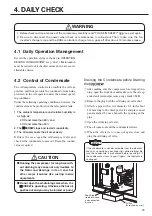
Page 21: ...ining the Condensate before Starting the After making sure the compressor has stopped run ning open the front door and make sure the oil sep arator tank internal pressure gauge reads 0 MPa Remove the plug with the oil drain port valve shut Attach a pipe with screw diameter 1 2 inch about 150 mm long to the drain port valve and place an oil pan furnished by user beneath the opening of the pipe Open...

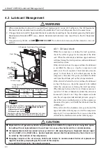
Page 22: ...ment and accumulate heat caused by its oxidization This may bring even fire in the worst case 2 Change lubricant and Oil Separator Element constantly according to the standard given by theTypical Maintenance Standard see p 42 44 Deteriorated Lubricant may result fire to the Oil Separator Element 3 Use genuine synthetic oil NEW HISCREW OIL NEXT for lubricant Avoid use of other brand or mix use with...

Page 23: ...tor tank as follows Remove the oil drain port s plug attach a pipe with screw diameter 1 2 inch about 150 mm long to the oil drain port valve place an oil pan beneath the opening of the pipe and open the valve After making sure the lubricant has been completely drained close the valve remove the pipe and mount the plug Drain oil from the oil cooler as follows Place the oil pan and unplug the oil d...

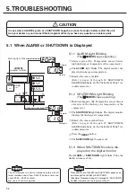
Page 24: ...ton The SHUTDOWN light becomes off 5 1 3 When SHUTDOWN code is dis played on the digital monitor The ALARM or SHUTDOWN light blinks Take the similar actions as above A L A RM 警 报 故 障 L OAD S HU T DOWN R EMO T E 负 载 远 程 开 S T A R 1 2 存 储 远 程 R EMO T E 显示转换 扩展模式 S T R 功 能 F UNC 重新设定 R E S E T S E L E C T W I D E 2 2 运行管理 R UNN I NG CON T R O L Warning Operate Shutdown light blink Warning light blink...

Page 25: ...mpressor automatically stops running and the START light goes off When the power supply is interrupted AUTO START light on the operation panel blinks The compressor will automatically restart 45 sec onds after POWER recovery R UNN I NG MOD E 运行状况 故 障 L OAD S HU T DOWN R EMO T E 负 载 远 程 电 源 P OWE R 自动启动 AU T O S T A R T 停 机 S T O P 开 机 S T A R T 2 1 Instantaneous power interruption means the instan...

Page 26: ... drop and imbalance Correct it if required Overcurrent Press the RESET button 17 Check and correct the capacity con trol settings if the discharge air pres sure is higher than the specification pressure Check the motor for insulation resis tance etc E0 53 SHUTDOWN On blinking Fan motor overload Yes Fan motor overcur rent dirty or clogged oil cooler and af ter cooler dirty or clogged controller s a...

Page 27: ...03 Instantaneous power interruption IPS No IPS of below 5 seconds Check the power supply IPS of 20 ms to 5 seconds 04 E0 21 ALARM On blinking Clogged air intake filter No Clogging of air intake filter Clean the air intake filter element Pressure differ ential of 7 47 kPa Press the RESET button 21 E0 22 ALARM On blinking Low oil Level option No 22 U100 Blinking ALARM On blinking Excessive load unload ...

Page 28: ...bnormality E20 Temperature trip DCBL Controller fan abnormality DCBL Controller fan rotation drop DCBL controller fan wire break E21 Temperature trip Cooling fin overheat Cooling fin suction hole cooler clogging high ambient temperature E22 Communication error 1 DCBL Controller internal communication abnormality Outside noise E23 Gate array error Gate array communication abnormality E24 Phase lackin...

Page 29: ...reased Suction Throttle Valve fault Disassemble and check O ring change Mechanical Sealing damage Replace Pressure Gauge indication fault Replace Relief Valve operated Excess Over Rated Pressure See Discharge air pressure increased above Relief Valve Incorrectly adjusted or failed Readjust repair or replace Discharge air Temp too high Faulty operation of cooling fan inverter Replace Suction Air Te...

Page 30: ...or Screws Refastening Fault Installation Add some mortar to settle the foundation levelly Abnormal noise from gears Foreign matter caught and or oil deteriorated Replace the parts Excessive Vibration Loose Bolts or Screws Refastening Fault Installation Add some mortar to settle the foundation levelly Unbalance of the unit due to Cooling Fan contamination Clean Fins Only if you installed an ammeter...

Page 31: ...pressed air to the lubricant is separated to the com pressed air and the lubricant in the Oil Separator Tank The separated lubricant is cooled in the Oil Cooler afterwards returns to the suction side of Compressor and exchange heat from compressed air again PS TH2 63E P TH1 63 SV Air Exhausted from Air Compressor Compressed Air Discharged Air for Cooling Unit Air into Air End Oil Discharge Coolant...

Page 32: ...ption Rate and Capacity Control System The Vplus HISCREW supports three V I and P capacity control modes As illustrated in the table below the capacity control system automatically activates the most desirable mode depending on the air consumption of your plant airline Compressed Air Consumption Operating Frequency Hz Mode of Capacity Control Pressures to Set Factory Settings MPa Allowable Setting...

Page 33: ...he operating frequency drops to 40 Hz equivalent to the air consumption of 30 As a result the 20P blowoff solenoid valve and 20US con trol solenoid valve operate to connect the ports NO and COM This closes the suction throttle valve and releases the oil separator tank s internal pressure to the atmosphere This is the stating of I mode capacity control The motor idles at its lowest possible speed t...

Page 34: ...g overtime and thus save the power as indicated by the illustration If you want to use this function contact your Hitachi distributor to modify the control circuit install an exter nal on off switch and set the cutout and cutin pres sures to as required Make sure that the LOAD light becomes on blinking and off when the HISCREW is respectively loading and unloading Note that this action of the LOAD...

Page 35: ... hooked in the wooden tie frame If the wire is dislocated from the frame while conveying the HISCREW a seri ous personal accident may happen The customer must provide wooden tie frame Crane After transport grounding do not move using tolls such as bars in fork holes of the common base for adjust ing installation position This is caused by common base and pack age distortion OSP 55VAN OSP 75VAN Mod...

Page 36: ... bration absorbable mat under the unit Such vibration may reach the compressor and damage its bearings Air Intake and Maintenance Space Right hand side space Keep a space of 0 5 m or more before setting up a power lines around the unit Install the HISCREW on a level floor Levelness within 1mm 1m Do not install the HISCREW near a wall Doing this may cause the operating sound to resonate and increas...

Page 37: ...d joint CAUTION 2 If there is concaved or upright piping in the run install a drain valve at the bottom of the run to pre vent the accumulation of the drain To connect the discharge pipe to your horizontal plant airline keep a space of more than 500 mm between the horizontal plant airline and the HISCREW rear cover so that the rear cover can be easily detached Drain Valve 7 4 3 Parallel operation ...

Page 38: ... not hinder maintenance accessi bility The air exhaust duct may transmit noise to the out doors Carefully select therefor a position of the air exhaust opening on the compressor room wall As required provide the air exhaust duct with sound insulation liners or a silencer In case where pressure loss of the duct is greater than 30 Pa on consideration of such pressure loss a ventilation fan with the ...

Page 39: ...ge circuit breaker for the circuit breaker For motor protection select the earth leakage circuit breaker based on the below table and equip to the main POWER line of the compressor If earth leakage circuit breaker other than Hitachi brand is used contact your Hitachi Authorized dealer for the detaile Type Frequency Hz Power Voltage V Rated Current A Starting Current A IPI Tripping Current A Rated ...

Page 40: ...nt and as a result DCBL controller and fan inverter fail 4 Install the Hitachi noise filters as below on the power supply if there are radios TV sets or any other electronics products around the HISCREW Description 55kW 75kW Functions Zero phase reactor 400 V class ZCL A Reduction of noise to radio etc Radio noise filter for input 400 V class CFI H Reduction of radiation noise from the power cord ...

Page 41: ...TANT 5 When you check the performance of the capacity control system in an initial startup operation setup the blow off stop valve that is mounted at the sec ondary part of the air receiver tank If you have to use the alternative stop valve at the discharge outlet of the HISCREW close it slowly and gently Closing it violently may cause the relief valve to operate or release the internal pressure T...

Page 42: ...7 6 7 55kW Wiring diagram 380 400 415 V 40 7 INSTRUCTIONS FOR INSTALLATION Instructions on Electrical Wiring ...

Page 43: ...7 6 8 75kW Wiring diagram 380 400 415 V 41 7 INSTRUCTIONS FOR INSTALLATION Instructions on Electrical Wiring ...

Page 44: ...or any other harsh operating environments 2 Maintenance item marked with Carry out by yourself or alternately order its servicing to the distributor Maintenance item marked with Order its servicing to the distributor Unless otherwise specified the interval is repetitive an interval of 2 years for example means every 2 years IMPORTANT CAUTION Before Maintenance work read To Use in Safety see p 2 ag...

Page 45: ... Cleaning Terminal refastening electric line cover check and cleaning Pipe joints Loose check Oil cooler Aftercooler Cleaning Lubricant genuine synthetic oil Replacement 21 Oil level gauge Replacement Consumable Parts Suction throttle valve Replacement Replace the cap seal valve plate and O ring Clean Piston of minimum pressure valve check valve Replacement Replace check valve spring O ring at the...

Page 46: ... 1M ohm or more at DC500 V Mega Electric panel instruments sensors Inspection Cleaning Terminal refastening electric line cover check and cleaning Pipe joints Loose check Oil cooler Aftercooler Cleaning Oil port O ring plug O ring Replacement Oil temperature control valve Inspection Cleaning Change O ring Consumable Parts Suction throttle valve Replacement Replace the cap seal valve plate and O ri...

Page 47: ...zed at or below 0 15 MPa Fully open the stop valve on discharge side within 3 minutes after the I mode capacity control is activat ed Make sure that the air end reloads accordingly If the air receiver tank capacity on the discharge side is less than recommended capacity the air end reloads before the pressure in the oil separator tank becomes stable pressure Do not operate the stop valve immediate...

Page 48: ...by the hand without use of a tool like filter wrench Oil Separator Tank Open Oil Filter Element Close Oil Pan CAUTION If a tool like filter wrench or pipe wrench is used to fasten the oil filter element ele ment s housing part may be damaged or deformed and will cause leak or breaking Be sure to fasten it by the hand tightly When the Oil Filter clogged lubricant sup ply to the compressor lessens a...

Page 49: ...ake filter element as soon as possible if the error code of an element clogging appears on the digital monitor Failure to do so will result in the reduction of the HISCREW capacity and in the worst case the damage of the air intake filter ele ment Air Intake Filter Housing Unfasten here Pull out Air Intake Filter Element Snap on fitting Air Intake Filter Cover Press the STOP button and disconnect ...

Page 50: ...it deteriorates its heat exchange and results lubricant and air insufficiently cooled Clean the cooler in such case Remove the front door or rear cover remove the main tenance cover and check if any dirt or dust adheres If so the cooler must be cleaned 400 500mm Air Cleaning Pipe It is easy to clean if the nose of the pipe is bent for about 20 to 40 mm from its end If the unit is heavily contamina...

Page 51: ...ernal pressure gauge reads 0 MPa Loosen a hexagonal portion of the minimum pres sure check valve body by spanner Do not unfas ten its lock nut portion remove the body in whole instead There are a pressure control spring minimum pres sure valve piston check valve spring check valve piston left on the element head side Take the part out and replace it with a new one if required Clean if there is dir...

Page 52: ...sen and detach Figure A Lower the housing and put it on the base Pull down the element slowly Pull so straight as not to bend the scavenge pipe in this action thus place the ele ment into the housing Figure B Remove the square ring Figure A Oil Separator Housing Special Tool Turn Pinch them Element Oil Separator Housing Square Ring Figure B If it is hard to loosen the housing when replacing wait u...

Page 53: ...ement s end plate closely with the head Be careful not to let the gasket out of its prop er position in this action Figure D Hold the housing with the both hands and contact its end to the head s threaded portion Be careful not to let the square ring out of the head Fasten the housing with both hands at first When hand fastening does not go any further using a specialized tool fasten it with the h...

Page 54: ...ce Schedule B of Air Compressor see p 44 Greasing Standard Operating condition Filling interval Filling amount When operating more than 3000hr year Every 6 months or 3000 hours whichever comes first 75g When operating 3000hr year or less Every 1 year or 3000 hours whichever comes first Be aware that grease replenish over the defined amount may cause overheated bear ing grease leakage etc CAUTION G...

Page 55: ...er elements to decrease or parts to become faulty When cooling fins are slightly stained After about 10 minutes elapse after disconnecting the power remove the front door Remove the fin cover 2 as shown in the figure Immediately after the power off the cooling fins and fin cover 2 are hot Wait until they are cooled down and then commence cleaning Check for dust in the controller cooling fin and bl...

Page 56: ...t contact your Hitachi distributor When cooling fins are heavily stained Disconnect the power wait for 10 minutes and remove the front door and right cover Then detach the motor duct Remove the fin cover 1 as shown in the figure Immediately after the power off the cooling fins and fin cover 1 are hot Wait until they are cooled down and then commence cleaning Check for dust in the DCBL controller c...

Page 57: ...sor screw block s rotation Smooth rotation Disassemble and check the com pressor screw block NOTE Grease the motor bearings Replace the lubricant Replace in whole Check power cables and terminals for deterioration or rusting No deterioration nor rusting Replace it with new one NOTE Ask your dealer or Hitachi regional office for information The compressor air end screw block can have rustings if no...

Page 58: ...lt of misuse or negligence of warnings cautions and instructions as indicated on the labels on the product and the Instruction Manual 3 Product failed or damaged as a result of repair or modification by anyone other than HITACHI and an authorized HITACHI s distributor who is not professional with the product 4 Product failed or damaged as a result of not using HITACHI genuine parts 5 Product s par...

Page 59: ...g 143 Rubber coupling 144 Motor Bearing DE 145 Motor Bearing ODE 146 Motor Fan 147 Motor Base 148 Grease Reservoir 149 Felt Not an item of the standard accessories 001 ITEM NO DESCRIPTION 001 Compressor Air End Assembly 002 Casing 003 D Casing 004 Male Rotor 006 Female Rotor 008 D Cover 009 65 Roller Bearings 011 50 3 Triserial Ball Bearings for 55kW 011 60 3 Triserial Ball Bearings for 75kW 012 5...

Page 60: ...sher 158 Plain Washer 163 Motor Bearing ODE 164 Motor Bearing DE 390 Aftercooler 391 Oil Cooler 55kW 75kW Cooler and Cooling Fan 269 263 262 264 270 271 265 267 266 ITEM NO DESCRIPTION 262 Operation Panel 263 Option Cover 264 Seat instrumental panel 265 Operation Printed Circuit Board 266 Cord Tube OPE 267 Cover printed circuit board 269 Rubber Bush 270 Cord 1 OPE 271 Cord 2 OPE Instrumental Panel...

Page 61: ...sembly 072 Case 074 Unloader Cover 075 Piston 076 Unloader Spring 1 077 Valve Plate 078 Shaft 079 Unloader Spring 2 083 O Ring 090 Bush Metal 092 Cap Seal 094 O Ring 097 Air Intake Filter 098 Air Intake Filter Element 099 Indicator 103 Band 1 104 Suction Pipe 105 Band 2 107 Joint ITEM NO DESCRIPTION 204 O Ring 205 Minimum Pressure Valve Piston 206 Check Valve Piston 252 Spring minimum pressure val...

Page 62: ...ine oil 4 L 064 Lubricant HITACHI genuine oil 20 L 065 Special tools for oil separator 066 Body Oil Filter 067 O Ring 192 Stop Valve 1 2 inch 201 Element Head Not an item of the standard accessories 203 244 059 058 225 193 240 251 229 254 227 226 203 244 059 058 225 193 240 251 229 254 226 ITEM NO DESCRIPTION 058 Thermistor 2 059 Thermistor 1 193 Check Valve 203 Minimum pressure Check Valve 225 Pr...

Page 63: ... Oil Filter Element 181 O Ring 184 O Ring 186 Oil Piping 1 187 Oil Piping 2 188 Oil Piping 3 189 Joint 1 elbow 190 Magnet Rubber 194 O Ring 195 Plug OTCV Oil Temperature Control Valve 55kW 75kW ITEM NO DESCRIPTION 033 Nipple oil filter 039 O Ring 042 Cover OTCV body 060 OTCV 173 Check Valve 179 Oil Filter Element 181 O Ring 184 O Ring 186 Oil Piping 1 187 Oil Piping 2 188 Oil Piping 3 189 Joint 1 ...

Page 64: ...ESCRIPTION 062 O Ring 202 Discharge Pipe 1 207 Discharge Pipe 2 214 O Ring 215 Gasket 223 Magnet Rubber 510 Discharge Pipe 3 ITEM NO DESCRIPTION 062 O Ring 202 Discharge Pipe 1 207 Discharge Pipe 2 214 O Ring 215 Gasket 223 Magnet Rubber 224 Magnet Rubber 510 Discharge Pipe 4 55kW 75kW Discharge Air Piping ...

Page 65: ...n Duct 2 412 Fan Duct 3 413 Fan Duct 4 414 Fan Duct 5 415 Cover 1 cooler 416 Cover 2 cooler 417 Cover 3 cooler 418 Base cooler 419 Rubber Bush 75kW 55kW Air Intake Duct Air Exhaust Duct ITEM NO DESCRIPTION 096 Air intake cover 399 Maintenance Cover 400 Motor Duct 405 Cover 4 cooler 406 Fan Duct 6 407 Mount 1 cooler 408 Mount 2 cooler 409 Mount 3 cooler 410 Fan Duct 1 411 Fan Duct 2 412 Fan Duct 3 ...

Page 66: ... name plate 449 NEXT name plate 450 Fixing bracket 1 451 Fixing bracket 2 452 Fixing bracket 3 453 Piping bracket 454 Cover discharge pipe 455 Rubber Bush 475 Noise Proofing Plate ITEM NO DESCRIPTION 420 Common Base 421 Front Center Frame 422 Left Frame front corner 423 Right Frame front corner 424 Left Frame rear corner 425 Right Frame rear corner 426 Right Cover 427 Left Cover 428 Door 1 429 Rea...

Page 67: ...Fuse 5A 307 Rubber Bush 308 Rubber Bush 309 Rubber Bush 316 Communication board 323 Cooling Fan starter 326 Guard cooling fan 332 Cover starter 333 Rubber Bush 334 Relay 335 Transformer 336 Fuse ITEM NO DESCRIPTION 282 Starter Panel 284 Cover fin 1 285 DCBL Controller 286 Cover fin 2 287 Controller Printed Circuit Board 288 Fan Inverter 289 Power Printed Circuit Board 290 Smoothing Capacitor 291 C...

Page 68: ...harge Air Pressure MPa Suction Air Temperature Discharge Air Temperature Lubricant Replenishment liter Remarks Start Stop Control Range 0 to 40 Control Range 100 or below Parts Replacement Other matters and To be Recorded 66 12 OPERATION RECORD LOGBOOK ...

Page 69: ...Integral Operating Hours h Discharge Air Pressure MPa Suction Air Temperature Discharge Air Temperature Lubricant Replenishment liter Remarks Start Stop Control Range 0 to 40 Control Range 100 or below Parts Replacement Other matters and To be Recorded ...

Page 70: ...L NEXT genuine synthetic oil Lubricating oil filling amount L 26 36 Total weight kg 1 220 1 390 Size Width Depth Height mm 2 000 1 200 1 800 NOTE 1 Discharge air capacity is a converted value according to the suction condition of the compressor 2 Discharge pressure indicates gauge pressure 3 Discharge air temperature varies depending on ambient temperature load ratio etc The interphase voltage unb...

Page 71: ...uency Hz 50 50 400V Class Power Voltage V 380 400 415 380 400 415 Rated output current A 120 3 8 Rated input current A 116 110 106 MODEL OSP 75VAN Main Motor Fan Motor Output Rating 75 2 2 Frequency Hz 50 50 400V Class Power Voltage V 380 400 415 380 400 415 Rated output current A 165 5 5 Rated input current A 158 150 145 ...

Page 72: ...ations for reference in the future Printed in Japan HIA 640D 2015 7 Hitachi Industrial Equipment Nanjing Co Ltd Model OSP kW Hz Compressor Serial No Installed on day month year Start Up on day month year Purchased from Phone Sales Person ...

Reviews: