HIGH POWER E-COMPACT TV TRANSMITTERS: from 0 to 25
MEDIUM POWER E-COMPACT TV TRANSMITTERS: from 0 to 30
ºC
LOW POWER E-COMPACT TV TRANSMITTERS: from 0 to 35
HIGH POWER AND MEDIUM POWER E-COMPACT TV TRANSMITTERS: from 0 to 80%
LOW POWER E-COMPACT TV TRANSMITTERS: from 0 to 90%
Hitachi Kokusai Linear Equipamentos Eletrônicos S/A
Current
Gauge
(mm2)
Current
Gauge
(mm2)
Current
Gauge
(mm2)
Current
Gauge
(mm2)
Current
Gauge
(mm2)
Current
Gauge
(mm2)
M220
P+N+G
1 phase with neutral : 220Vac between phase and neutral
13
1.5
25
6
38
10
50
16
75
35
100
50
B220
2P+G
2 phases, without neutral: 220Vac between phases
13
1.5
25
6
38
10
50
16
75
35
100
50
T220
3P+G
3 phases, without neutral: 220Vac between phases
13
1.5
23
4
23
4
34
10
45
10
68
25
T380
3P+N+G
3 phases with neutral: 380Vac between phases, 220Vac
between phase and neutral
13
1.5
13
1.5
13
1.5
26
6
26
6
39
10
(*)
(*)
(*)
2.8 kVA
5.5kVA
8.3kVA
11kVA
16.5kVA
22kVA
EC708HP
EC701HP
EC702HP
EC703HP
EC704HP
EC706HP
TOPIC
The grounding system, to which Hitachi Kokusai Linear’ TV transmitter will be attached, must be designed and implemented by trained professionals. An
improper grounding system may put at risk, not just the equipment but the life of the professionals working in the shelter. To be considered proper, the
grounding must have a resistance of no more than 5
.
G
R
O
U
N
D
IN
G
A
C
M
A
IN
S
It is important to have isolation between energy stations of the shelter and the TV transmitter, which is achieved with the usage of isolator transformers.
Thus is guaranteed that no AC Mains’ transient coming from the shelter will be passed on to the TV transmitter or vice-versa. Besides, Hitachi Kokusai
Linear’ TV transmitter features switching power supplies that require purely sinusoidal power input, and voltage regulators or no-breaks without isolator
transformers have no assurance of a purely sinusoidal outputs. The isolator transformer must also be exclusive to the TV transmitter and its dimensioning
must use the same standards employed in the dimensioning of the voltage regulator or no-break, ie, at least 30% higher than the TV transmitter’s specified
consumption (in KVA).
S
T
A
B
IL
IT
Y
IN
S
U
L
A
T
IO
N
W
IR
E
G
A
U
G
E
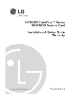
MINIMUM INFRASTRUCTURE REQUIREMENTS
The Atmospheric Discharge Protection System – ADPS is comprised by the lightning rod and its accessories. The tower and shelter must be protected
against Atmospheric Discharges, through a FRANKLIN lightning rod, dimensioned and installed by the USER, following the criteria defined by NBR 5419
(in its latest version) and including all the station installations within the protection zone defined in the Level I electro-geometric model of rolling spheres.
The usage of coaxial protectors is advisable for cables which connect internal and external equipments (antennas, microwave heads, tower converters).
These shields are devices featuring gas-sparklers that short-circuit to the ground, any surges discharged in the coaxial cables. Must be within the shelter,
close to the equipment and with its ground wire bound in the equipment’s rack ground.
L
IG
H
T
N
IN
G
R
O
D
A
D
P
S
T
E
M
P
E
R
A
T
U
R
E
H
U
M
ID
IT
Y
The relative humidity within the shelter is a solely important factor for best performance and longer lifetime of the equipment. Hitachi Kokusai Linear’
devices must operate in dry environments; this is also achieved by proper Climate Control Systems. In accordance with transmission power, the relative
humidity must be:
Should never be condensation, as water may damage internal circuitry of the transmitter.
C
L
IM
A
T
E
C
O
N
T
R
O
L
P
R
O
T
E
C
T
O
R
S
ANNEX I
(*)
Due to the number of amplifiers not be multiple of 3, the current is not equal to the 3 phases (unbalanced system).
The current quoted in the table is more loaded phase to sizing effect of conductors and protection.
Said gauge is the minimum recommended for the transmitter in question, if the cable length is large, consider voltage drop in the cable maximum of 5%
The section of the neutral conductor should be the same phase.
The section of the ground conductor may be 10% of the phase conductors, not being less than 1mm2.
The settings on the green background with table are the recommended settings for each transmitter model.
For best performance and longer lifetime of the equipment, it is important that the shelter features a strict climate control, through the installation of an air-
conditioning system. For project purposes, consider the thermal dissipation specified to the transmitter (BTU/h), the thermal dissipation of the other devices
in the shelter, the thermal charge cause by solar incidence and all other thermal charges within the shelter. It is recommended that the internal pressure of
the shelter is slightly positive, avoiding the entrance of outside contaminants. According to the transmission power, the internal temperature of the shelter
should be:
In the event of damage caused by inefficient or improper Climate Control Systems within the shelter, will automatically result in the suspension of the
warranty terms.
•
•
•
•
•
ºC
ºC