6 MAINTENANCE
6-46
6.3 Replacing the Battery Module
When the battery module (model LQZ500) is discharged to a predetermined low level, the model-
LQP525 or LQP527 CMU module’s ALARM LED is lit. In this case, obtain error log
information by using the Base System and check that the “battery low” condition is reported in
the displayed error information. If the power to the CMU module is turned off in a “battery
low” condition, the contents of its main memory may be lost. To prevent this, back them up in
files by using the backup restore system before you turn off the power to the CMU module.
The programs in memory are loaded in from the flash memory, so they need not be backed up in
files for battery replacement.
The model LQZ500 can back up the CMU module’s main memory continuously for
approximately one year of power-off condition. However, if the LQZ500 is used in a severe
environment of high temperature and high humidity, replace it before its useful life reaches one
year. Of course, when the ALARM LED is lit before the one-year limit, replace it.
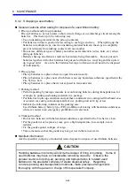
Notes on battery replacement
z
Replace the LQZ500 module only when the following conditions are met: 1) the LQP525 or
LQP527 module’s ALARM LED is lit and 2) the “battery low” condition is reported in the
displayed error log information.
z
Replace the LQZ500 module only in a power-on condition.
z
The internal clock may stop due to the “battery low” condition. Check the system time
after you have replaced the LQZ500 module.
6.3.1 Replacement
procedure
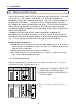
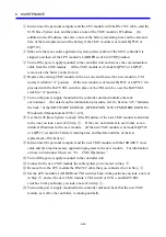
When the LQZ500 module needs to be replaced, the replacement must be done in a power-on
condition by performing the following procedure:
①
Discharge any static electricity from your body
before starting your replacement work.
②
Disconnect the battery cable from the LQP525
or LQP527 module.
③
Remove the battery module from the mount
base.
Summary of Contents for CMU LPQ520
Page 1: ......
Page 2: ......
Page 17: ...This Page Intentionally Left Blank ...
Page 19: ...This Page Intentionally Left Blank ...
Page 23: ...This Page Intentionally Left Blank ...
Page 28: ...v 6 4 Replacing the CMU Module 6 49 6 4 1 Replacing the module 6 49 6 5 Trouble Report 6 51 ...
Page 30: ...1 SPECIFICATIONS ...
Page 38: ...2 NAMES AND FUNCTIONS OF EACH PART ...
Page 43: ...This Page Intentionally Left Blank ...
Page 44: ...3 MOUNTING AND WIRING ...
Page 52: ...4 OPERATION ...
Page 85: ...This Page Intentionally Left Blank ...
Page 86: ...5 USER GUIDE ...
Page 101: ...This Page Intentionally Left Blank ...
Page 102: ...6 MAINTENANCE ...


