2 NAMES AND FUNCTIONS OF EACH PART
2-2
2.1 Names and Functions of Each Part
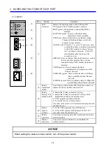
(1) LQP520
No. Name
Function
①
LED
indicators
Indicate the operating status of the CMU module.
RUN (green): The C-mode program is running.
PROT (green): Writing from a task to SEQ RAM is
disabled.
ALARM: Glows to indicate that an error that is not serious
enough to disrupt CMU module operations is
detected.
USER: Glows to indicate an invalid user setting.
ERR: Glows to indicate that a hardware error, serious fault
or any other problem that is serious enough to
disrupt CMU module operations is detected.
②
T/M switch
0: Normal mode of operation
A: CMU program operations disabled
F: Test mode (Do not set this position.)
Any other value is reserved for maintenance purposes and
should not be set.
③
Station
number
switches
0, 0: The CMU operates at the set IP address.
F, F: The CMU operates at IP address 192.192.192.1.
Any other value should not be set.
④
Ethernet
LINE
indicator
Glows to indicate that the CMU is connected to an
Ethernet line.
⑤
Ethernet
ACTIVE
indicator
Glows when the CMU is communicating data on Ethernet.
⑥
Ethernet
connector
Connector used for 10BASE-T and 100BASE-TX
communication.
NOTICE
When setting the station number switch, turn off the power switch.
LQP520
T/M
RUN
ALARM
ERR
CMU
USER
PROT
U
ST.No.
L
10/100
BASE-T
ACTIVE
/LINE
S10V
①
②
③
④
⑤
⑥
Summary of Contents for CMU LPQ520
Page 1: ......
Page 2: ......
Page 17: ...This Page Intentionally Left Blank ...
Page 19: ...This Page Intentionally Left Blank ...
Page 23: ...This Page Intentionally Left Blank ...
Page 28: ...v 6 4 Replacing the CMU Module 6 49 6 4 1 Replacing the module 6 49 6 5 Trouble Report 6 51 ...
Page 30: ...1 SPECIFICATIONS ...
Page 38: ...2 NAMES AND FUNCTIONS OF EACH PART ...
Page 43: ...This Page Intentionally Left Blank ...
Page 44: ...3 MOUNTING AND WIRING ...
Page 52: ...4 OPERATION ...
Page 85: ...This Page Intentionally Left Blank ...
Page 86: ...5 USER GUIDE ...
Page 101: ...This Page Intentionally Left Blank ...
Page 102: ...6 MAINTENANCE ...

